71BD36-02-2-AJN Grayhill Inc, 71BD36-02-2-AJN Datasheet - Page 4
71BD36-02-2-AJN
Manufacturer Part Number
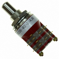
71BD36-02-2-AJN
Description
SW RTRY DP 1/4A .5-.75" SLDR TRM
Manufacturer
Grayhill Inc
Series
71r
Type
Rotaryr
Datasheet
1.71BD30-01-1-AJN.pdf
(14 pages)
Specifications of 71BD36-02-2-AJN
Angle Of Throw
36°
Number Of Positions
2 ~ 5
Number Of Decks
2
Number Of Poles Per Deck
2
Circuit Per Deck
DP5T
Contact Rating @ Voltage
0.25A @ 28VDC
Actuator Type
Flatted (6.35mm dia)
Mounting Type
Panel Mount
Termination Style
Solder Lug
Orientation
Vertical
No. Of Poles
2
No. Of Switch Positions
5
Contact Current Ac Max
300mA
Contact Voltage Ac Max
115V
Contact Voltage Dc Max
30V
Circuitry
DP5T
No. Of Decks
2
Current, Rating
1/4 A
Dielectric Strength
500 VAC
Number Of Poles
2
Termination
Solder
Contact Current Max
250mA
Rohs Compliant
Yes
Lead Free Status / RoHS Status
Lead free / RoHS Compliant
Other names
GH7314


DIMENSIONS: Metric
CIRCUIT DIAGRAMS: Standard, Military and Metric PC Mount
Grayhill, Inc. • 561 Hillgrove Avenue • LaGrange, Illinois
4mm Diameter Shaft: Style EF and ESF
30° Angle
of Throw
Grayhill part number and date code marked on detent cover label. Customer part number marked on request.
22,23 ± 0,4
0,51 ± 0,08 TYP.
Ø 17,45
± 0,4
No. of
Decks
1
2
3
4
5
6
ONE POLE
TWO POLE
6,00 + 0,00 –0,08
19,33
24,87
30,40
35,94
41,48
54,13
Dim.
A
TERMINAL
NO. 1
12
12
C L
BUSHING
FLATS
All dimensions are in millimeters
11
11
OF
Dim.
0,79
0,79
0,79
0,79
0,79
7,92
10 9 8 7 6 5 4 3
C2
10 9 8 7 6 5 4 3 2 1
B
Ø 4,00 ± 0,03
Approx.
Circuit is Viewed From Shaft End and Shown in Position No. 1
Weight
Grams
12
14
16
18
20
22
C1
8,00 ± 0,3
Decks
No. of
2
C1
10
11
12
7
8
9
C
1
C L
25,00 ± 0,51
L
60525-5997 • USA • Phone: 708-354-1040 • Fax: 708-354-2820 • www.grayhill.com
M7 X 0,75
THREAD
OF BUSHING
KEYWAY OR
FLATS
10,46 ± 0,25
59,66
65,20
70,74
76,28
81,81
87,35
Dim.
A
Dim.
7,92
7,92
7,92
7,92
7,92
7,92
.0,38
± 0,03
TYP.
B
Note: Common location for a single pole per
STUD PROJECTION
C
L
(SEE CHARACTER-
deck switch. For common location on
two pole switches see circuit diagrams.
DIM. A ± 1,17
C
Approx.
L
Weight
Grams
36° Angle
of Throw
Multi-Deck Rotary Switches
24
26
28
30
32
34
C
L
DIM. B REF.
2,79 ± 0,25
TYP.
ISTICS)
SEE NOTE
BELOW
ONE POLE
TWO POLE
14,27
± 0,38
10 9 8 7 6 5 4 3 2 1
10 9 8 7 6 5 4 3 2 1
3,96 ± 0,25
3,96 ± 0,25
C2
18,42
± 0,04
TYP.
TYP.
SEE
NOTE
30° and 36° Angle of Throw may be
interposed on either shaft diameter.
SEE
NOTE
36° Angle of Throw
30° Angle of Throw
Rear Views
C
C L
L
Ø 12,7
± 0,38
Ø 12,7
± 0,38
C
L
C L
C L
C1
C1
C L
C L
C L
C L
C L
3,18 ± 0,25
OF BUSHING
KEYWAY OR
FLATS
3,18 ± 0,25
0,94 ± 0,13
TYP.
0,94 ± 0,13
TYP.
1,91 ± 0,13
TYP.
1,91 ± 0,13
TYP.
7,62 ± 0,25
7,62 ± 0,25
TYP.
TYP.
9,35
REF.
REF.
9,35
Rotary
5
Related parts for 71BD36-02-2-AJN
Image
Part Number
Description
Manufacturer
Datasheet
Request
R

Part Number:
Description:
SW RTRY SP 1/4A .5-.75" SLDR TRM
Manufacturer:
Grayhill Inc
Datasheet:

Part Number:
Description:
Rotary Switch, 1/4" Shaft, Adjustable Stop, 36°
Manufacturer:
Grayhill Inc
Datasheet:
Part Number:
Description:
Rotary Switch, 1/4" Shaft, Adjustable Stop, 36°
Manufacturer:
Grayhill Inc
Datasheet:
Part Number:
Description:
Rotary Switch, 1/4" Shaft, Adjustable Stop, 36°
Manufacturer:
Grayhill Inc
Datasheet:
Part Number:
Description:
Rotary Switch, 1/4" Shaft, Adjustable Stop, 36°
Manufacturer:
Grayhill Inc
Part Number:
Description:
Rotary Switch, 1/4" Shaft, Adjustable Stop, 36°
Manufacturer:
Grayhill Inc

Part Number:
Description:
Rotary Switch, 1/4" Shaft, Adjustable Stop, 36°
Manufacturer:
Grayhill Inc
Datasheet:
Part Number:
Description:
Rotary Switch, 1/4" Shaft, Adjustable Stop, 36°
Manufacturer:
Grayhill Inc
Datasheet:

Part Number:
Description:
Rotary Switch, 1/4" Shaft, Adjustable Stop, 36°
Manufacturer:
Grayhill Inc
Datasheet:
Part Number:
Description:
Rotary Switch, 1/4" Shaft, Adjustable Stop, 36°
Manufacturer:
Grayhill Inc
Part Number:
Description:
Rotary Switch, 1/4" Shaft, Adjustable Stop, 36°
Manufacturer:
Grayhill Inc
Part Number:
Description:
Rotary Switch, 1/4" Shaft, Adjustable Stop, 36°
Manufacturer:
Grayhill Inc