71BD36-02-2-AJN Grayhill Inc, 71BD36-02-2-AJN Datasheet - Page 10
71BD36-02-2-AJN
Manufacturer Part Number
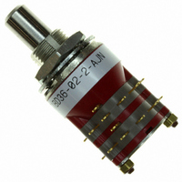
71BD36-02-2-AJN
Description
SW RTRY DP 1/4A .5-.75" SLDR TRM
Manufacturer
Grayhill Inc
Series
71r
Type
Rotaryr
Datasheet
1.71BD30-01-1-AJN.pdf
(14 pages)
Specifications of 71BD36-02-2-AJN
Angle Of Throw
36°
Number Of Positions
2 ~ 5
Number Of Decks
2
Number Of Poles Per Deck
2
Circuit Per Deck
DP5T
Contact Rating @ Voltage
0.25A @ 28VDC
Actuator Type
Flatted (6.35mm dia)
Mounting Type
Panel Mount
Termination Style
Solder Lug
Orientation
Vertical
No. Of Poles
2
No. Of Switch Positions
5
Contact Current Ac Max
300mA
Contact Voltage Ac Max
115V
Contact Voltage Dc Max
30V
Circuitry
DP5T
No. Of Decks
2
Current, Rating
1/4 A
Dielectric Strength
500 VAC
Number Of Poles
2
Termination
Solder
Contact Current Max
250mA
Rohs Compliant
Yes
Lead Free Status / RoHS Status
Lead free / RoHS Compliant
Other names
GH7314


SPECIFICATIONS: Electrical Ratings, Others
Grayhill, Inc. • 561 Hillgrove Avenue • LaGrange, Illinois
Electrical Ratings
General
Charts: Charts shown are for non-shorting
(break before make) contacts. Measurements
were made at 25°C and 68% relative humidity.
The load life curves show the number of
rotational cycles which can be expected for
the voltage, current and type of load. Thus,
for a standard style switch with a 300
milliampere 115 Vac resistive load, the
expected life is 15,000 cycles. Reducing the
load to 200 milliamperes increases the life to
25,000 cycles. Life limiting or failure criteria
are listed in the rating sections which follow.
Cycles: A cycle is a 360° rotation and a return
through all switch positions to the starting
position.
Voltage: As listed in charts.
250
200
150
100
250
200
150
100
600
500
400
300
200
100
800
700
600
500
400
300
200
100
50
50
VOLTAGE 115 VAC
10
10
10
10
VOLTAGE 115 VAC
Standard
CYCLES x 1000
CYCLES x 1000
Military
CYCLES x 1000
CYCLES x 1000
(250 MILLIHENRIES)
OR 30 VDC
RESISTIVE
(250 MILLIHENRIES)
OR 30 VDC
RESISTIVE
VOLTAGE 30 VDC
VOLTAGE 30 VDC
25
INDUCTIVE
25
25
25
INDUCTIVE
50
50
50
50
Electrical Ratings
Standard Style
Curves are based on the following failure
criteria:
Contact Resistance: 50 milliohms maximum
(20 milliohms initially).
Insulation Resistance: 1,000 megohms
minimum between terminals and shaft. (50,000
megohms initially).
Voltage Breakdown: 500 Vac minimum
between mutually insulated parts.
Current Rating: These switches will carry 4
amperes with a maximum contact temperature
rise of 20°C. If the life limiting characteristics
are less critical than those shown above, if
elevated temperatures or reduced pressures
are involved, Grayhill can predict the switch
life for the application.
Meet the Following Requirements of MIL-
DTL-3786: Moisture Resistance: Medium and
High Shock; Vibration (10 to 2,000 cps);
Thermal Shock (-65°C to 85°C); Salt Spray,
Explosion; and Stop Strength (10 in-lb).
Electrical Ratings
Military Style
Curves are based on the following failure
criteria:
Qualified to the following MIL-DTL-3786/39
circuit values: (also see standard style
description.) The Series 71 has been tested to
meet the requirements of MIL-DTL-3786, Style
SR39, the majority of which are listed here. At
85°C approximately 68% relative humidity and
sea level pressure, the switches have been
tested to make and break the following loads,
as
milliamperes at 28 Vdc resistive; 75
milliamperes at 115 Vac resistive.
The switches have also been tested at reduced
barometric pressure (70,000 feet), 25°C at
approximately 68% relative humidity to make
and break the following loads as stated in MIL-
DTL-3786/39: 50 milliamperes, 28 Vdc resistive;
20 milliamperes, 115 Vac resistive. When
tested to the above loads at stated conditions,
the Series 71 switches meet the following life-
limiting criteria after 25,000 cycles of operation
in accordance with MIL-DTL-3786/39.
60525-5997 • USA • Phone: 708-354-1040 • Fax: 708-354-2820 • www.grayhill.com
stated
in
MIL-DTL-3786/39:
Multi-Deck Rotary Switches
125
Contact Resistance: 50 milliohms maximum
after life.
Insulation Resistance: 1,000 megohms
minimum between terminals and shaft.
Dielectric Strength: 500 Vac (atmospheric
pressure) and 350 Vac (reduced pressure)
between mutually insulated parts.
The Series 71 also meets the requirements
of MIL-DTL-3786/39 for moisture resistance,
stop strength, rotational torque, vibration (10
through 2,000 cps), medium and high shock,
salt spray, explosion, thermal shock (-65°C
to 85°C) and terminal pull. When tested at sea
level, 25°C and 68% relative humidity with
failure criteria of 50 milliohms maximum
contact resistance and 500 Vac breakdown
voltage, these switches will make and break
250 milliamps at 28 Vdc inductive (250
millihenries) 500 milliamps at 28 Vdc resistive:
500 milliamps at 115 volts Vac, 60 hertz
resistive, for 10,000 cycles of operation.
Additional Characteristics
Standard and Military Styles
Rotational Torque: 4-32 ounce-inches, (28-
230 N•mm) depending on the number of
poles per deck and the number of decks.
Contacts: Shorting or non-shorting wiping
contacts with over 100 grams of contact
force.
Shaft Flat Orientation: Opposite first position
pole no. 1 (See Circuit Diagrams).
Terminals: Switches are provided with full
circle of terminals regardless of the number
of active positions.
Extended Studs: Switches of 6 or more
decks (or concentric switches of 4 or more)
have longer studs and extra stud nuts for
recommended double end mounting. Stud
hole size is
thread.
Stop Strength: 10 pound-inches.
Mounting Bushing Strength: 10 pound-
inches.
1
/
16
" diameter for #0-80 NF-2A
Rotary
11
Related parts for 71BD36-02-2-AJN
Image
Part Number
Description
Manufacturer
Datasheet
Request
R

Part Number:
Description:
SW RTRY SP 1/4A .5-.75" SLDR TRM
Manufacturer:
Grayhill Inc
Datasheet:

Part Number:
Description:
Rotary Switch, 1/4" Shaft, Adjustable Stop, 36°
Manufacturer:
Grayhill Inc
Datasheet:
Part Number:
Description:
Rotary Switch, 1/4" Shaft, Adjustable Stop, 36°
Manufacturer:
Grayhill Inc
Datasheet:
Part Number:
Description:
Rotary Switch, 1/4" Shaft, Adjustable Stop, 36°
Manufacturer:
Grayhill Inc
Datasheet:
Part Number:
Description:
Rotary Switch, 1/4" Shaft, Adjustable Stop, 36°
Manufacturer:
Grayhill Inc
Part Number:
Description:
Rotary Switch, 1/4" Shaft, Adjustable Stop, 36°
Manufacturer:
Grayhill Inc

Part Number:
Description:
Rotary Switch, 1/4" Shaft, Adjustable Stop, 36°
Manufacturer:
Grayhill Inc
Datasheet:
Part Number:
Description:
Rotary Switch, 1/4" Shaft, Adjustable Stop, 36°
Manufacturer:
Grayhill Inc
Datasheet:

Part Number:
Description:
Rotary Switch, 1/4" Shaft, Adjustable Stop, 36°
Manufacturer:
Grayhill Inc
Datasheet:
Part Number:
Description:
Rotary Switch, 1/4" Shaft, Adjustable Stop, 36°
Manufacturer:
Grayhill Inc
Part Number:
Description:
Rotary Switch, 1/4" Shaft, Adjustable Stop, 36°
Manufacturer:
Grayhill Inc
Part Number:
Description:
Rotary Switch, 1/4" Shaft, Adjustable Stop, 36°
Manufacturer:
Grayhill Inc