A16-CTM Omron, A16-CTM Datasheet - Page 248
A16-CTM
Manufacturer Part Number
A16-CTM
Description
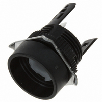
CASE ROUND 16 SERIES MOMENTARY
Manufacturer
Omron
Type
Round Caser
Series
A16r
Specifications of A16-CTM
Switch Type
Push Button Switch
Operating Temp Range
-10C to 55C
Illumination
Not Illuminated
Mounting Style
Snap On
Lead Free Status / RoHS Status
Lead free / RoHS Compliant
For Use With
A16 Series
Lead Free Status / RoHS Status
Lead free / RoHS Compliant, Lead free / RoHS Compliant
Other names
A16CTM


A3P
A3PJ/M2PJ (Rectangular Models)
A3PA/M2PA (Square Models)
246
Assembly/Disassembly
1. Locking/Unlocking Positive Cap Lock Mechanism
2. Mounting Pushbutton
3. Removing/Mounting Cap
4. Mounting Colored Plate
5. Mounting Character Plate (Character Frame) and Legend
Plate
A3PJ
OMRON logo
Be sure to mount the Pushbutton with the correct orienta-
tion. Align the groove on the Pushbutton, the projections
in the Switch, and the LED contact piece before pushing
the Pushbutton into the Switch.
When dismounting the Pushbutton, use the Extractor
(A3PJ-5080) for easy dismounting.
Insert the A3PA from the open side into the theft-preven-
tion stopper.
Place the colored plate on the plunger case with the dull
side of the colored plate facing downward. With A3PJ
split-screen models, be sure that the projections on the
upper surface of the colored plate face outward. For the
A3PA, make sure that the flat plate is facing upwards.
Mount the legend plate for the A3PJ under the layered
surfaces and mount the cap, as shown below.
Unlock
Projection
LED contact piece
Lock
Diagram shows A3PA model.
A3PA
Positive cap stopper
Flat plate
Groove
Note: Built-in LEDs cannot be replaced.
6. Mounting and Replacing LED and Incandescent Lamps
7. LED Rated Voltage Display (LED Models Only)
8. Mounting Switch onto Panel
•
•
A3PA
A3PJ
Individual Mounting and Barrier Mounting
Multiple Barrier Mounting (A3PJ)
Colored plate
If using an A3PA (square) model with one incandescent
lamp, insert the lamp in the center hole.
The LED rated voltage is shown between the built-in re-
sistors on the back of the lighting unit. Use within a range
of $ 5%.
When mounting the Switch, push it into the panel cutout
from the front of the mounting panel by holding it with the
logo mark ‘‘OMRON” facing downward.
When mounting a number of Switches in line on the pan-
el, link the Switches with spacing barriers in between,
attach mounting barriers at both sides of this block of
Switches and, pushing in on the mounting barriers at the
side, insert the Switches into the panel cutout together.
Legend plate
Note: Display is on the back.
Transparent cap
(Light baffle)
Rated voltage display
OMRON logo
(Character plate)
A3P
Related parts for A16-CTM
Image
Part Number
Description
Manufacturer
Datasheet
Request
R

Part Number:
Description:
LAMP LED 12VDC 16 SERIES RED
Manufacturer:
Omron
Datasheet:

Part Number:
Description:
LAMP LED 6VAC/DC 16 SERIES GREEN
Manufacturer:
Omron
Datasheet:
Part Number:
Description:
LAMP LED 6VAC/DC 16 SERIES RED
Manufacturer:
Omron
Datasheet:

Part Number:
Description:
LAMP LED 6VAC/DC 16 SERIES YEL
Manufacturer:
Omron
Datasheet:

Part Number:
Description:
SWITCH PB SQUARE MOM SPDT GREEN
Manufacturer:
Omron
Datasheet:

Part Number:
Description:
SWITCH PB SQUARE MOM SPDT WHITE
Manufacturer:
Omron
Datasheet:
Part Number:
Description:
SWITCH PB SQUARE MOM SPDT YELLOW
Manufacturer:
Omron
Datasheet:
Part Number:
Description:
SWITCH PB RECTANG MOM SPDT BLUE
Manufacturer:
Omron
Datasheet:
Part Number:
Description:
SWITCH PB RECTANG MOM SPDT YEL
Manufacturer:
Omron
Datasheet:
Part Number:
Description:
SWITCH PB SQUARE MOM SPDT BLUE
Manufacturer:
Omron
Datasheet:
Part Number:
Description:
SWITCH PB SQUARE MOM SPDT RED
Manufacturer:
Omron
Datasheet:
Part Number:
Description:
SWITCH PB RECTANG MOM SPDT GREEN
Manufacturer:
Omron
Datasheet:
Part Number:
Description:
SWITCH PB RECTANG MOM SPDT RED
Manufacturer:
Omron
Datasheet:

Part Number:
Description:
SWITCH PB RECTANG MOM SPDT WHITE
Manufacturer:
Omron
Datasheet:
Part Number:
Description:
SWITCH PB ROUND MOM SPDT BLUE
Manufacturer:
Omron
Datasheet: