A16-5 Omron, A16-5 Datasheet - Page 25
A16-5
Manufacturer Part Number
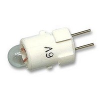
A16-5
Description
LAMP INCAND 6VAC/DC 16 SERIES
Manufacturer
Omron
Type
Incandescent Lamp, 6 Volts AC/DCr
Series
A16r
Specifications of A16-5
Supply Voltage
5V
Base Type
Bi-Pin
Average Bulb Life
3000h
Svhc
No SVHC (15-Dec-2010)
Current Rating
60mA
Nom Operating Voltage
5V
Operating Lifetime
3000h
Voltage Rating
5V
Voltage Rating Vac
5V
Illumination
Illuminated
Contact Rating
60 mAmps at 6 Volts AC/DC
Height
13 mm
Mounting Style
Snap In
Termination Style
Tabs
Lamp Base Type
Bi-Pin
Rohs Compliant
Yes
Lead Free Status / RoHS Status
Lead free / RoHS Compliant
For Use With
A16 Series
Lead Free Status / RoHS Status
Lead free / RoHS Compliant, Lead free / RoHS Compliant


A16
Removing and Mounting the Pushbutton
Removing the Lamp
Removing from the Pushbutton End
Removing from the Switch End
The Lamp can be removed by hand once the Switch is removed
using the A16Z-5080 Extractor.
Installing the Lamp
When mounting the Lamp, make sure it is facing the direction shown
in the following diagram. Insert the Lamp while matching the pro-
truding part of the Lamp and the small guides on the outer surface of
the Case.
The Lamp can be mounted from the Pushbutton end by using the
A16Z-5080 Extractor. The lamp can be mounted by following the
opposite procedure for removing the Lamp.
76
1. Remove the Pushbutton as shown in the following diagram. If
2. To attach the Pushbutton, push until it clicks into place.
Mounting and Replacing the
Pushbutton
the Pushbutton cannot be removed by hand, use the
A3PJ-5080 Extractor.
Protruding part
Lamp
Grip the Lamp with the
A16Z-5080 Extractor and
pull to remove.
Pushbutton
Mounting the A16Z Dust Cover
Note: Recommended panel thickness: 0.5 to 2 mm.
Mounting the A16Z Switch Guard
Note: Recommended panel thickness: 0.5 to 2 mm.
Set
A16ZJ-5060
1. Separate the Dust Cover into 2 parts: cover A and cover B.
2. Insert the Case into cover B.
3. Mount these parts together onto the panel.
4. From the back of the panel, mount the lock ring and secure
5. Insert cover A into cover B. Ensure that the entire perimeter of
6. Mount the Switch Unit to the Case.
1. Insert the Case into the Switch Guard.
2. Mount these parts together onto the panel.
3. From the back of the panel, mount the lock ring and secure
4. Attach the Switch Unit to the Case.
with the mounting nut.
cover A is securely attached to cover B by pressing in
different directions.
with the mounting nut.
Switch Unit
Pushbutton Unit
Switch Guard
Mounting nut
Lock ring
Panel
Switch Unit
Cover A
(transparent)
Pushbutton Unit
Cover B
(black)
Panel
Lock ring
Mounting nut
A16
Related parts for A16-5
Image
Part Number
Description
Manufacturer
Datasheet
Request
R

Part Number:
Description:
SWITCH PB SQUARE MOM SPDT GREEN
Manufacturer:
Omron
Datasheet:

Part Number:
Description:
SWITCH PB SQUARE MOM SPDT WHITE
Manufacturer:
Omron
Datasheet:
Part Number:
Description:
SWITCH PB SQUARE MOM SPDT YELLOW
Manufacturer:
Omron
Datasheet:
Part Number:
Description:
SWITCH PB RECTANG MOM SPDT BLUE
Manufacturer:
Omron
Datasheet:
Part Number:
Description:
SWITCH PB RECTANG MOM SPDT YEL
Manufacturer:
Omron
Datasheet:
Part Number:
Description:
SWITCH PB SQUARE MOM SPDT BLUE
Manufacturer:
Omron
Datasheet:
Part Number:
Description:
SWITCH PB SQUARE MOM SPDT RED
Manufacturer:
Omron
Datasheet:
Part Number:
Description:
SWITCH PB RECTANG MOM SPDT GREEN
Manufacturer:
Omron
Datasheet:
Part Number:
Description:
SWITCH PB RECTANG MOM SPDT RED
Manufacturer:
Omron
Datasheet:

Part Number:
Description:
SWITCH PB RECTANG MOM SPDT WHITE
Manufacturer:
Omron
Datasheet:
Part Number:
Description:
SWITCH PB ROUND MOM SPDT BLUE
Manufacturer:
Omron
Datasheet:
Part Number:
Description:
SWITCH PB ROUND MOM SPDT GREEN
Manufacturer:
Omron
Datasheet:
Part Number:
Description:
SWITCH PB ROUND MOM SPDT RED
Manufacturer:
Omron
Datasheet:
Part Number:
Description:
SWITCH PB ROUND MOM SPDT WHITE
Manufacturer:
Omron
Datasheet:
Part Number:
Description:
SWITCH PB ROUND MOM SPDT YELLOW
Manufacturer:
Omron
Datasheet: