0012-0023 Cherry Electrical, 0012-0023 Datasheet - Page 43
0012-0023
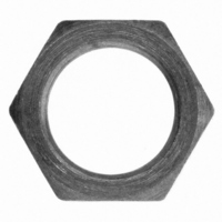
Manufacturer Part Number
0012-0023
Description
HEX NUT FOR E13 SERIES SWITCH
Manufacturer
Cherry Electrical
Type
Sub-Miniature Snap-Action Switchesr
Series
0012r
Specifications of 0012-0023
Accessory Type
Hex Nut
Contact Form
SPDT
Contact Rating
25 Amps at 125 Volts, 250 Volts
Actuator
Lever, Hinge
Termination Style
Screw
Color
Natural
For Use With/related Products
CH100, CH101, CKN318, CH322, CH324, CH329
For Use With
CH574 - SWITCH SNAP SPDT .1A QC TERMCH329 - SWITCH SNAP 20A W/THD BUSHINGCH324 - SWITCH SNAP 15A W/THD BUSHINGCH322 - SWITCH SNAP 15A W/THD BUSHINGCH318 - SWITCH SNAP 25A W/THD BUSHINGCH101 - SWITCH SNAP SPDT 15A QC TERMCH100 - SWITCH SNAP SPDT 15A QC TERM
Lead Free Status / RoHS Status
Lead free / RoHS Compliant
Lead Free Status / RoHS Status
Lead free / RoHS Compliant, Lead free / RoHS Compliant
Other names
00120023
CH284
CH284


Dimensions
Actuator Specifications
*Measured above reference line. Refer to dimensional drawing above. **Actuator tolerance ±.0.031 inches (0.79mm).
Ordering Information
Specifications subject to change without notice.
Actuator
Code Force Code Force Rating
KW
Series/Prefix
G
A
C
E
Type
J
G
M
Q
A
B
C
D
E
F
T
Light
J
(14.68 ± 0.38)
0.578 ± 0.015
Oper. Pos.
25
25
25
50
75
A Dim.
B Dim.
Mtg Screw
Pretravel
(1.19)
Ref. Line
0.047
Max.
Switch
M
Type
B
D
F
H
K
S
(10.31 ± 0.13)
L
0.406 ± 0.005
Standard
A
Mounting Holes
0.114 (2.90) 0.122 (3.10)
0.126 (3.20) 0.134 (3.40)
± 0.005
(±0.13)
A
inches (mm)
Ø B ± 0.005
4-40 (3)
U.S.
150
150
150
150
225
75
75
75
(± 0.13)
(10.31)
0.406
0.109
(2.77)
KWC, KWE
0.109
(2.77)
Current
50mA
KWA,
10A
15A
15A
25A
1A
3A
5A
25
25
14
15
16
15
6
8
4
9
8
Metric
(22.23 ± 0.13)
0.875 ± 0.005
Notes
3, 5
(28.96)
1.140
(20.24)
Maximum Operating Force (gms.)
1
1
1
1
1
3
2
0.797
COM
(13.51)
KWG
0.532
50
50
27
12
30
15
31
18
29
16
7
(8.13)
0.320
*Only available with 15A.
Notes:
1.
2.
3.
4. Available in 10A and lower,
5. Available with 0.250 x 0.032″ terminals only.
Code Temperature Rating
D
C
150°C, 200°C. VDE rated for 150°C only.
C
150°C, 200°C. VDE rated for 85°C only.
C
for 100,000 cycles at 85°C and 150°C.
A
B
C
D
E
UL
UL
UL
NC
NO
US
US
US
(9.14)
0.360
KWD, KWJ
KWB, KWF
rated for 100,000 cycles at 85°C,
rated for 100,000 cycles at 85°C,
rated for 100,000 cycles at 85°C only.
Dog Leg Terminal
85°C UL/CUL
150°C UL/CUL
200°C UL/CUL
85°C UL/CUL/VDE*
150°C UL/CUL/VDE
(14.48)
(14.48)
0.570
0.570
0.282 (7.16)
75
75
40
18
44
23
10
46
26
43
24
0.119
(3.02)
(3.96)
0.156
0.112 (2.85)
0.032 (0.81) or
0.020 (0.51)
KWK, KWM
ØA ± 0.005
0.368
(9.35)
KWH,
150
150
80
36
88
45
20
92
52
85
47
(± 0.13)
C
(5.99)
0.236
UL
US
rated
Notes:
*Applicable to 0.032 (0.8) thick by
Ø 0.070 (1.78)
0.250 (6.3) wide tabs only.
SPDT switch (as shown) with 3 terminals
NO, NC, and COM. SPST switch will have
one terminal (NO or NC), and a COMMON
terminal depending on switch type.
0.057 (1.45)
KWS
225
225
120
132
138
127
54
67
30
77
71
*PCB terminals are lateral to case only.
Code Terminal Type
Code Mounting Holes
Q
P
W
Q
R
S
T
V
A
B
4
0.160
(4.06)
0.062 x 0.032 (1.57 x 0.81) PCB*
0.187 x 0.020 (4.75 x 0.51) Straight
0.187 x 0.020 (4.75 x 0.51) Dog Leg
0.187 x 0.032 (4.75 x 0.81) Straight
0.187 x 0.032 (4.75 x 0.81) Dog Leg
0.250 x 0.032 (6.35 x 0.81) Straight
0.250 x 0.032 (6.35 x 0.81) Dog Leg
U.S.
Metric
0.250* (6.35) or
0.187 (4.75)
(15.88)
0.625
0.174* (4.42) or
0.125 (3.18)
Pre-Travel
Maximum
(13.01)
(1.63)
(3.26)
(7.22)
(2.95)
(5.85)
(2.80)
(5.08)
(3.05)
(5.54)
inches
0.047
(1.19)
0.064
0.128
0.284
0.116
0.230
0.512
0.110
0.200
0.120
0.218
(mm)
inches (mm)
(14.31/15.06)
(15.78/14.85)
(16.18/14.45)
(17.25/13.38)
(16.11/14.52)
(16.90/13.74)
(18.78/11.86)
(19.26/17.72)
(19.84/17.14)
(21.65/19.96)
(22.28/19.32)
0.563/0.593
0.621/0.585
0.637/0.569
0.679/0.527
0.634/0.572
0.665/0.541
0.739/0.467
0.758/0.698
0.781/0.675
0.852/0.786
0.877/0.761
Code Configuration
Operating
A
B
C
inches
Point*
(mm)
Normally Open
Normally Closed
Double Throw
Actuators
Standard type snap over hinged lever
and roller actuators are available in
choice of two pivot positions. Lengths
are dimensioned from centerline of
switch upper mounting hole as shown here.
Auxiliary Actuator
Mounting
Recommended mounting screw size:
#4-40 Round head. Recommended torque
on screw: 3 inch lbs. max.
Over-Travel
Minimum
A C A
(10.33)
(1.27)
(1.29)
(2.16)
(4.62)
(1.88)
(3.71)
(2.23)
(2.92)
(2.43)
(4.39)
inches
0.050
0.051
0.085
0.182
0.074
0.146
0.407
0.088
0.115
0.096
0.173
(mm)
Straight
Roller
Simulated
Roller
High Ratio
†
Available as internal mounting only.
Code Type
A
B
C
D
E
F
G
J
M
Y
Q
W
T
†
†
Actuation Length
Max. Movement
Button
Straight SR
Straight SR
Straight SR
Straight HR
Straight HR
Straight HR
SIM Roller SR
SIM Roller HR
Roller SR
Roller SR
Roller HR
Roller HR
Differential
inches
0.010
(0.25)
0.012
(0.31)
0.030
(0.76)
0.051
(1.30)
0.021
(0.54)
0.041
(1.05)
0.091
(2.32)
0.020
(0.51)
0.036
(0.92)
0.022
(0.56)
0.039
(1.00)
(mm)
Snap Over Actuators
(13.51)
0.532
Actuation Length
(8.13)
0.320
0.865 (21.97)
1.400 (35.56)
2.722 (69.14)
1.077 (27.36)
1.612 (40.95)
2.934 (74.52)
1.254 (31.85)
1.466 (37.24)
0.810 (20.57)
1.340 (34.04)
1.022 (25.96)
1.552 (39.42)
Standard Ratio
inches (mm)
Actuation
Length**
(21.97)
(35.56)
(69.14)
(27.36)
(40.94)
(74.52)
(31.85)
(37.24)
(34.04)
(39.42)
inches
0.865
1.400
2.722
1.077
1.612
2.934
1.254
1.466
1.340
1.552
(mm)
—
—
43
Related parts for 0012-0023
Image
Part Number
Description
Manufacturer
Datasheet
Request
R

Part Number:
Description:
MOUSE, LASER WIRELESS IR, USB, BLUE/BLK
Manufacturer:
Cherry Electrical
Datasheet:

Part Number:
Description:
Manufacturer:
Cherry Electrical
Datasheet:
Part Number:
Description:
Manufacturer:
Cherry Electrical
Datasheet: