0012-0023 Cherry Electrical, 0012-0023 Datasheet - Page 33
0012-0023
Manufacturer Part Number
0012-0023
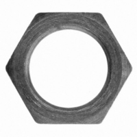
Description
HEX NUT FOR E13 SERIES SWITCH
Manufacturer
Cherry Electrical
Type
Sub-Miniature Snap-Action Switchesr
Series
0012r
Specifications of 0012-0023
Accessory Type
Hex Nut
Contact Form
SPDT
Contact Rating
25 Amps at 125 Volts, 250 Volts
Actuator
Lever, Hinge
Termination Style
Screw
Color
Natural
For Use With/related Products
CH100, CH101, CKN318, CH322, CH324, CH329
For Use With
CH574 - SWITCH SNAP SPDT .1A QC TERMCH329 - SWITCH SNAP 20A W/THD BUSHINGCH324 - SWITCH SNAP 15A W/THD BUSHINGCH322 - SWITCH SNAP 15A W/THD BUSHINGCH318 - SWITCH SNAP 25A W/THD BUSHINGCH101 - SWITCH SNAP SPDT 15A QC TERMCH100 - SWITCH SNAP SPDT 15A QC TERM
Lead Free Status / RoHS Status
Lead free / RoHS Compliant
Lead Free Status / RoHS Status
Lead free / RoHS Compliant, Lead free / RoHS Compliant
Other names
00120023
CH284
CH284


Actuator Specifications — European Versions
Actuator
KD/MD*
*On light force D41 and D42, auxiliary actuators MD, ML, LD and LL are made out of Aluminum.
Ordering Information — European Versions
EN standard on all D4 European designs.
Specifications subject to change without notice.
ML/KL*
MA/KA
JD/LD*
LA/JA*
LL/JL*
Code
Series/Prefix
Type
D4
AA
RA
RD
TD
UA
SA
TA
1
2
3
4
5
8
9
0.1(0.5)A, 250V
3(1)A, 250V
6(2)A, 250V
10(3)A, 250V
16(4)A, 250V
10(3)A, 400V~
(Std. force only)
21(8)A, 250V
N/A
EN61058
Switch
Type
3
190 / 45
120 / 32
190 / 50
Std / Light
170 / 45
190 / 50
110 / 30
D41-D43
110 / 28
86 / 22
55 / 14
86 / 22
50 / 14
40 / 10
25 / 6
0.1A, 125/250VAC
3A, 125/250VAC
1/10HP, 250VAC
5A, 1/4HP, 125/250VAC
10A, 1/2HP, 125/250VAC
15A, 1/2HP, 125/250VAC
21A, 1HP, 125VAC
2HP, 250VAC
10A, 1/2HP, 125/250VAC
6A, 30VDC
Maximum Operating Force (Gms.)
UL1054
Std / Light
330 / 75 440 / 100 180
144 / 40
200 / 55
215 / 55
330 / 85 440 / 115 200
285 / 75 400 / 100
180 / 50
320 / 85 440 / 115
144 / 40
86 / 25
60 / 17
40 / 10
86 / 22
D44
200 / 50
120 / 30
260 / 70
280 / 70
Std / Light
256 / 65
200 / 50
120 / 30
90 / 22
56 / 13
D45
** Not available for D45 or D48 versions.
Code Terminal Type
* Not available for D48 European versions.
(EN Standard)
W9
Mounting
C1
C3
PA
PB
Q1
Q3
R1
R3
D48
150
100
180
110
110
European
A1
B8
P4
P5
S1
V1
V3
Y5
Z5
Mounting
75
45
35
20
75
50
Holes
Metric
Holes
Welding
Short Solder*
0.110 x 0.032 (2.8 x 0.8) QC, Bifurcated Straight**
0.110 x 0.032 (2.8 x 0.8) QC, Bifurcated Dog Leg**
0.047 x 0.020 (1.2 x 0.5) PCB, Underside*
0.047 x 0.020 (1.2 x 0.5) PCB, Rear*
0.047 x 0.032 (1.2 x 0.8) PCB, Housing Side*
0.047 x 0.032 (1.2 x 0.8) PCB, Cover Side*
0.187 x 0.032 (4.8 x 0.8) QC Straight*
0.187 x 0.032 (4.8 x 0.8) QC Dog Leg*
0.187 x 0.020 (4.8 x 0.5) QC, Straight**
0.187 x 0.020 (4.8 x 0.5) QC, Dog Leg**
Solder with Temp. Stop
0.250 x 0.032 (6.3 x 0.8) QC, Straight
0.250 x 0.032 (6.3 x 0.8) QC, Dog Leg
Screw*
0.250 x 0.032 (6.3 x 0.8) QC, 5mm Grid
0.250 x 0.032 (6.3 x 0.8) QC, 7mm Grid
D41–D45
(12.7)
0.047
0.126
0.200
0.087
0.087
0.051
0.047
0.087
0.047
0.126
0.200
0.299
0.500
(1.2)
(3.2)
(5.1)
(2.2)
(2.2)
(1.3)
(1.2)
(2.2)
(1.2)
(3.2)
(5.1)
(7.6)
Pre-Travel
Maximum
NO NC DT Force
G
N
S
inches
1
7
(mm)
3
2
8
H
P
T
0.063
0.063
0.150
0.252
0.346
0.575
(14.6)
0.067
0.150
0.244
0.118
0.118
0.067
0.118
(1.7)
(3.8)
(6.2)
(3.0)
(3.0)
(1.7)
(1.6)
(3.0)
(1.6)
(3.8)
(6.4)
(8.8)
D48
inches (mm)
M
3
9
R
U
Oper. Temp.
Light
Light
Light
Std.
Std.
0.776/0.839
0.764/0.850
0.744/0.870
0.764/0.850
0.768/0.846
0.780/0.835
0.559/0.599
0.567/0.630
0.579/0.618
0.551/0.646
0.535/0.661
0.433/0.764
(19.7/21.3)
(19.4/21.6)
(18.9/22.1)
(19.4/21.6)
(19.5/21.5)
(19.8/21.2)
D41–D45, D48
(14.2/15.2)
(14.4/16.0)
(14.7/15.7)
(14.0/16.4)
(13.6/16.8)
(12.0/18.4)
(11.0/19.4)
Operating
0.47/0.72
inches
Point
(mm)
125°C
150°C
Index
85°C
V3
D41–D45
0.051
0.063
0.035
0.091
0.142
0.185
0.031
0.039
0.087
0.142
0.063
0.063
0.039
(1.0)
(2.2)
(3.6)
(1.6)
(1.6)
(1.0)
(1.3)
(1.6)
(0.9)
(2.3)
(3.6)
(4.7)
(7.9)
Over Travel
Minimum
inches
(mm)
SR = Standard Ratio, Back Hole • HR = High Ratio, Front Hole
Additional actuators available upon request.
Code Actuator Type
AA
L
0.031
0.071
0.118
0.051
0.051
0.031
K
M
R
S
U
0.047
0.055
0.031
0.071
0.126
0.169
0.283
J
L
T
(0.8)
(1.8)
(3.0)
(1.3)
(1.3)
(0.8)
(1.2)
(1.4)
(0.8)
(1.8)
(3.2)
(4.3)
(7.2)
D48
Button
SS Lever SR
SSLever HR
Lever SR
Lever HR
Roller SR
Sim. Roller SR
Roller HR
Sim. Roller HR
Max. Movement
D41–D45
0.016
0.031
0.051
0.024
0.020
0.012
0.012
0.024
0.012
0.031
0.051
0.067
0.098
(0.3)
(0.6)
(0.3)
(0.8)
(1.3)
(1.7)
(2.5)
(0.4)
(0.8)
(1.3)
(0.6)
(0.5)
(0.3)
Differential
inches
(mm)
0.012
0.024
0.012
0.031
0.051
0.067
0.098
0.012
0.031
0.047
0.020
0.012
(0.3)
(0.8)
(1.2)
(0.5)
(0.5)
(0.3)
(0.3)
(0.6)
(0.3)
(0.8)
(1.3)
(1.7)
(2.5)
0.02
D48
0.835 (21.2)
0.835 (21.2)
0.811 (20.6)
0.811 (20.6)
0.988 (25.1)
0.988 (25.1)
1.01 (25.7)
1.01 (25.7)
Code
D
—
A
D41–D45
(21.8) (22.0)
(24.8) (24.8)
(27.4) (27.4)
(23.8) (24.0)
(23.8) (24.0)
(21.8) (22.0)
0.638
(16.2)
0.740
(18.8)
0.661
(16.8)
0.780
(19.8)
0.874
(22.2)
0.992
(25.2)
1.210
(30.8)
0.858 0.866
0.976 0.976
1.080 1.078
0.937 0.945
0.937 0.945
0.858 0.866
Max. Rest
Position
Actuation Length
inches
1.34 (34.1)
1.52 (38.6)
1.4 (35.6)
1.4 (35.6)
(mm)
—
—
—
—
—
D
(16.2)
(18.8)
(16.8)
(19.8)
(22.2)
(25.2)
(30.8)
0.638
0.740
0.661
0.780
0.874
0.992
1.210
D48
2.75 (69.9)
2.93 (74.4)
2.75 (69.9)
2.93 (74.4)
D41–D45, D48
Actuation
inches (mm)
Length
inches
(25.7)
(21.2)
(35.6)
(40.1)
(69.9)
(74.4)
0.811
(20.6)
(34.1)
(38.6)
0.988
(25.1)
0.988
(25.1)
0.811
(20.6)
—
—
—
—
0.835
—
L
(mm)
1.34
1.52
1.01
1.40
1.58
2.75
2.93
—
33
Related parts for 0012-0023
Image
Part Number
Description
Manufacturer
Datasheet
Request
R

Part Number:
Description:
MOUSE, LASER WIRELESS IR, USB, BLUE/BLK
Manufacturer:
Cherry Electrical
Datasheet:

Part Number:
Description:
Manufacturer:
Cherry Electrical
Datasheet:
Part Number:
Description:
Manufacturer:
Cherry Electrical
Datasheet: