MS5534-CM Measurement Specialties Inc., MS5534-CM Datasheet
MS5534-CM
Specifications of MS5534-CM
Available stocks


Related parts for MS5534-CM


MS5534-CM Summary of contents
Page 1
... Bit data word from a pressure and temperature dependent voltage. Additionally the module contains 6 readable coefficients for a highly accurate software calibration of the sensor. MS5534C is a low power, low voltage device with automatic power down (ON/OFF) switching. A 3-wire interface is used for all communications with a microcontroller ...
Page 2
... Fig. 2: Pin configuration of MS5534CM. Type Master clock (32.768 kHz) P Positive supply voltage I Programming enable N Negative programming voltage Conditions MS5534-CP MS5534-CM June 16th, 2008 Function Ground Serial data clock Data output Data input Min Max Unit Notes -0 -40 +125 C 5 bar 10 bar 1 2 ...
Page 3
... During conversion the sensor will be switched on and off in order to reduce power consumption; the total on time within a conversion is about 2 ms. 3) This value can be reduced by switching off MCLK while MS5534C is in standby mode strongly recommended that a crystal oscillator be used because the device is sensitive to clock jitter. A square-wave form of the clock signal is a must ...
Page 4
ELECTRICAL CHARACTERISTICS DIGITAL INPUTS Parameter Symbol Input High Voltage V IH Input Low Voltage V IL Signal Rise Time t r Signal Fall Time t f DIGITAL OUTPUTS Parameter Symbol Output High Voltage V OH Output Low Voltage V OL ...
Page 5
... PRESSURE OUTPUT CHARACTERISTICS With the calibration data stored in the interface IC of the MS5534C the following characteristics can be achieved: Parameter Resolution Absolute Pressure Accuracy Relative Pressure Accuracy Relative Pressure Error over Temperature Long-term Stability Maximum Error over Supply Voltage NOTES 1) A stable pressure reading of the given resolution requires taking the average subsequent pressure values due to noise of the ADC ...
Page 6
... Pressure (mbar) ADC-value D2 vs Temperature (typical Temperature (° C) Absolute Pressure Accuracy after Calibration, 2nd order compensation 300 400 500 600 700 800 Pressure (mbar) June 16th, 2008 -40° C 25° C 125° C 900 1000 1100 ...
Page 7
... DA5534C_003.doc 0005534C1175 ECN1118 Temperature Error Accuracy vs temperature (typical Temperature (° C) Pressure Error Accuracy vs temperature (typical Temperature (°C) June 16th, 2008 Temperature error (standard calculation) Temperature error (with 2nd order calculation) 100 120 Perror(1000,1st order) Perror(1000,2nd order) Perror(800,1st order) Perror(800,2nd order) ...
Page 8
... DA5534C_003.doc 0005534C1175 ECN1118 Pressure error vs supply voltage (typical) 2.8 3 3.2 Voltage (V) Temperature error vs supply voltage (typical) 2.8 3 3.2 Voltage (V) June 16th, 2008 1000mbar 800mbar 3.4 3.6 300mbar 3.4 3 ...
Page 9
... FUNCTION GENERAL The MS5534C consists of a piezoresistive sensor and a sensor interface IC. The main function of the MS5534C is to convert the uncompensated analogue output voltage from the piezoresistive pressure sensor to a 16-Bit digital value, as well as providing a 16-Bit digital value for the temperature of the sensor. ...
Page 10
... C6: Temperature coefficient of the temperature ( Refer to application note AN509 for limits of coefficients and calculated results) Read digital pressure value from MS5534C D1 (16 Bit) Read digital temperature value from MS5534C D2 (16 Bit) Calculate calibration temperature UT1 = 8*C5+20224 Calculate actual temperature Difference between actual temperature and reference ...
Page 11
... In order to obtain best accuracy over the whole temperature range recommended to compensate for the non-linearity of the output of the temperature sensor. This can be achieved by correcting the calculated temperature and pressure by a second order correction factor. The second-order factors are calculated as follows: TEMP < 200 ...
Page 12
... Fig. 1. The SCLK (Serial clock) signal initiates the communication and synchronises the data transfer with each Bit being sampled by the MS5534C on the rising edge of SCLK and each Bit being sent by the MS5534C on the rising edge of SCLK. The data should thus be sampled by the microcontroller on the falling edge of SCLK and sent to the MS5534C with the falling edge of SCLK. The SCLK-signal is generated by the microprocessor’ ...
Page 13
Conversion start for temperature measurement and ADC-data-out "D2": start of conversion sequence: START+T-measurement Bit0 Bit1 Bit2 Bit3 Bit4 Bit5 Bit6 Bit7 Bit8 Bit9 Start-bit Setup-bits Stop-bit Calibration data read out sequence for word 1/ word 3: sequence: coefficient read + ...
Page 14
... LIGHT SENSITIVITY The MS5534C is sensitive to sunlight, especially to infrared light sources. This is due to the strong photo effect of silicon. As the effect is reversible there will be no damage, but the user has to take care that in the final product the sensor cannot be exposed to direct light during operation ...
Page 15
... DECOUPLING CAPACITOR Particular care must be taken when connecting the device to power supply µ F tantalum capacitor must be placed as close as possible of the MS5534C's VDD pin. This capacitor will stabilise the power supply during data conversion and thus, provide the highest possible accuracy. APPLICATION EXAMPLE: ALTIMETER SYSTEM USING MS5534C MS5534C is a circuit that can be used in connection with a microcontroller in mobile altimeter applications ...
Page 16
... DEVICE PACKAGE OUTLINES Fig. 8: Device package outlines of MS5534CP . DA5534C_003.doc 0005534C1175 ECN1118 June 16th, 2008 16 ...
Page 17
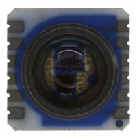
... DEVICE PACKAGE OUTLINES Fig. 9: Device package outlines of MS5534CM . DA5534C_003.doc 0005534C1175 ECN1118 June 16th, 2008 17 ...
Page 18
... RECOMMENDED PAD LAYOUT Pad layout for bottom side of MS5534C soldered onto printed circuit board Pad layout for top side of MS5534C soldered onto printed circuit board DA5534C_003.doc 0005534C1175 ECN1118 Fig. 10: Layout for bottom side Fig. 11: Layout for top side June 16th, 2008 ...
Page 19
... Special care has to be taken to not touch the protective gel of the sensor during the assembly. The MS5534C can be mounted with the cap down or the cap looking upwards. In both cases it is important to solder all contact pads. The Pins PEN and PV shall be left open or connected to VDD. Do not connect the Pins ...
Page 20
... ESD PRECAUTIONS The electrical contact pads are protected against ESD HBM (human body model therefore essential to ground machines and personal properly during assembly and handling of the device. The MS5534C is shipped in antistatic transport boxes. Any test adapters or production transport boxes used during the assembly of the sensor shall equivalent antistatic material ...
Page 21
... ORDERING INFORMATION Product Product Code Barometer Module MS5534-CP with plastic cap Barometer Module MS5534-CM with metal cap FACTORY CONTACTS Intersema Sensoric SA Ch. Chapons-des-Prés 11 CH-2022 BEVAIX SWITZERLAND NOTICE Intersema reserves the right to make changes to the products contained in this data sheet in order to improve the design or performance and to supply the best possible products ...