VSKT500-12 Vishay, VSKT500-12 Datasheet - Page 3
VSKT500-12
Manufacturer Part Number
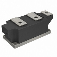
VSKT500-12
Description
SCR DBL 2SCR 1200V 500A MAGNAPAK
Manufacturer
Vishay
Datasheet
1.VSKH500-12.pdf
(8 pages)
Specifications of VSKT500-12
Structure
Series Connection - All SCRs
Number Of Scrs, Diodes
2 SCRs
Voltage - Off State
1200V
Current - Gate Trigger (igt) (max)
200mA
Current - On State (it (av)) (max)
500A
Current - On State (it (rms)) (max)
785A
Current - Non Rep. Surge 50, 60hz (itsm)
17800A, 18700A
Current - Hold (ih) (max)
500mA
Mounting Type
Chassis Mount
Package / Case
SUPER MAGN-A-PAK
Rated Repetitive Off-state Voltage Vdrm
1200 V
Off-state Leakage Current @ Vdrm Idrm
100 mA
Holding Current (ih Max)
500 mA
Mounting Style
Screw
Breakover Current Ibo Max
18700 A
Gate Trigger Current (igt)
200 mA
Gate Trigger Voltage (vgt)
3 V
Repetitive Peak Forward Blocking Voltage
1200 V
Lead Free Status / RoHS Status
Contains lead / RoHS non-compliant
Other names
*IRKT500-12
IRKT500-12
IRKT500-12
IRKT500-12
IRKT500-12


Note
• Table shows the increment of thermal resistance R
Document Number: 94420
Revision: 02-Jul-10
TRIGGERING
PARAMETER
Maximum peak gate power
Maximum peak average gate power
Maximum peak positive gate current
Maximum peak positive gate voltage
Maximum peak negative gate voltage
Maximum DC gate current required to trigger
DC gate voltage required to trigger
DC gate current not to trigger
DC gate voltage not to trigger
THERMAL AND MECHANICAL SPECIFICATIONS
PARAMETER
Maximum junction operating
temperature range
Maximum storage temperature range
Maximum thermal resistance,
junction to case per junction
Maximum thermal resistance,
case to heatsink
Mounting torque ± 10 %
Approximate weight
Case style
R
CONDUCTION ANGLE
thJC
180°
120°
CONDUCTION
90°
60°
30°
SMAP to heatsink
DiodesAmericas@vishay.com, DiodesAsia@vishay.com,
(SUPER MAGN-A-PAK Power Modules), 500 A
busbar to SMAP
SINUSOIDAL CONDUCTION
For technical questions within your region, please contact one of the following:
Thyristor/Diode and Thyristor/Thyristor
VSKT500-..PbF, VSKH500-..PbF, VSKL500-..PbF
0.009
0.011
0.014
0.021
0.037
SYMBOL
SYMBOL
R
P
R
+V
-V
+I
T
P
thC-hs
V
V
I
G(AV)
I
T
thJC
Stg
GT
GD
GM
GD
GM
GT
GM
GM
J
thJC
when devices operate at different conduction angles than DC
DC operation
A mounting compound is recommended and
the torque should be rechecked after a period
of 3 hours to allow for the spread of the
compound.
See dimensions - link at the end of datasheet
T
T
T
T
T
J
J
J
J
J
RECTANGULAR CONDUCTION
= T
= T
= T
= 25 °C, V
= T
J
J
J
J
maximum, t
maximum, f = 50 Hz, d% = 50
maximum, t
maximum
TEST CONDITIONS
TEST CONDITIONS
ak
0.006
0.011
0.015
0.022
0.038
12 V
p
p
5 ms
5 ms
DiodesEurope@vishay.com
Vishay Semiconductors
TEST CONDITIONS
T
J
= T
J
maximum
- 40 to 130
- 40 to 150
VALUES
VALUES
12 to 15
SUPER MAGN-A-PAK
6 to 8
0.065
1500
0.02
0.25
200
2.0
3.0
5.0
3.0
10
20
10
www.vishay.com
UNITS
UNITS
UNITS
K/W
K/W
Nm
mA
mA
°C
W
A
V
V
V
g
3
Related parts for VSKT500-12
Image
Part Number
Description
Manufacturer
Datasheet
Request
R

Part Number:
Description:
SCR DBL 2SCR 800V 500A MAGNAPAK
Manufacturer:
Vishay
Datasheet:
Part Number:
Description:
SCR DBL 2SCR 1400V 500A MAGNAPAK
Manufacturer:
Vishay
Datasheet:
Part Number:
Description:
SCR DBL 2SCR 1600V 500A MAGNAPAK
Manufacturer:
Vishay
Datasheet:

Part Number:
Description:
SCR Modules 500 Amp 1200 Volt 785 Amp IT(RMS)
Manufacturer:
Vishay
Part Number:
Description:
SCR Modules 500 Amp 1400 Volt 785 Amp IT(RMS)
Manufacturer:
Vishay
Part Number:
Description:
SCR Modules 500 Amp 800 Volt 785 Amp IT(RMS)
Manufacturer:
Vishay
Part Number:
Description:
SCR Modules 500 Amp 1600 Volt 785 Amp IT(RMS)
Manufacturer:
Vishay

Part Number:
Description:
Thyristor/Diode and Thyristor/Thyristor
Manufacturer:
Vishay Siliconix
Datasheet:
Part Number:
Description:
357-036-542-201 CARDEDGE 36POS DL .156 BLK LOPRO
Manufacturer:
Vishay
Datasheet:
Part Number:
Description:
357-036-542-201 CARDEDGE 36POS DL .156 BLK LOPRO
Manufacturer:
Vishay
Datasheet:
Part Number:
Description:
357-036-542-201 CARDEDGE 36POS DL .156 BLK LOPRO
Manufacturer:
Vishay
Datasheet:
Part Number:
Description:
357-036-542-201 CARDEDGE 36POS DL .156 BLK LOPRO
Manufacturer:
Vishay
Datasheet:
Part Number:
Description:
357-036-542-201 CARDEDGE 36POS DL .156 BLK LOPRO
Manufacturer:
Vishay
Datasheet:
Part Number:
Description:
357-036-542-201 CARDEDGE 36POS DL .156 BLK LOPRO
Manufacturer:
Vishay
Datasheet:
Part Number:
Description:
357-036-542-201 CARDEDGE 36POS DL .156 BLK LOPRO
Manufacturer:
Vishay
Datasheet: