P102 Vishay, P102 Datasheet - Page 5
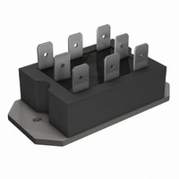
P102
Manufacturer Part Number
P102
Description
SCR HY-BRIDGE 600V 25A PACE-PAK
Manufacturer
Vishay
Specifications of P102
Structure
Bridge, Single Phase - SCRs/Diodes (Layout 1)
Number Of Scrs, Diodes
2 SCRs, 2 Diodes
Voltage - Off State
600V
Current - Gate Trigger (igt) (max)
60mA
Current - On State (it (rms)) (max)
25A (DC)
Current - Non Rep. Surge 50, 60hz (itsm)
357A, 375A
Current - Hold (ih) (max)
130mA
Mounting Type
Chassis Mount
Package / Case
6-PACE-PAK
Lead Free Status / RoHS Status
Lead free / RoHS Compliant
Current - On State (it (av)) (max)
-
Lead Free Status / Rohs Status
Details
Other names
*P102
Available stocks
Company
Part Number
Manufacturer
Quantity
Price

Company:
Part Number:
P1020NSE2DFB
Manufacturer:
Freescale Semiconductor
Quantity:
10 000
Company:
Part Number:
P1020NSE2FFB
Manufacturer:
Freescale Semiconductor
Quantity:
10 000
Company:
Part Number:
P1020NSE2HFB
Manufacturer:
FSL
Quantity:
27
Company:
Part Number:
P1020NSE2HFB
Manufacturer:
Freescale Semiconductor
Quantity:
10 000
Company:
Part Number:
P1020NSN2DFB
Manufacturer:
Freescale Semiconductor
Quantity:
10 000
Part Number:
P1020NSN2HFB
Manufacturer:
FREESCALE
Quantity:
20 000
Company:
Part Number:
P1020NXE2HFB
Manufacturer:
FSL
Quantity:
44
Part Number:
P1020NXE2HFB
Manufacturer:
FREESCALE
Quantity:
20 000
Company:
Part Number:
P1020NXN2HFB
Manufacturer:
FREESCA
Quantity:
1
Company:
Part Number:
P1020PSE2FDA
Manufacturer:
FSL
Quantity:
24


Document Number: 93754
Revision: 04-Nov-09
Dimensions
93754_06
93754_08
93754_09
350
300
250
200
150
Fig. 6 - Maximum Non-Repetitive Surge Current
0.01
100
1
0.1
0.1
10
10
0.0001
1
1
0.001
Per junction
Number of Equal Amplitude Half
Rectangular gate pul e
(a) Recommended load line for
(b) Recommended load line for
V
R
(DC operation)
teady tate value
thJC
D
rated dI/dt: 10 V, 20 Ω, t
rated dI/dt: 10 V, 65 Ω, t
Cycle Current Pulses (N)
At any rated load condition and with
rated V
= 2.24 K/W
I
D
RRM
10
applied following urge.
0.001
0.01
For technical questions, contact:
at 60 Hz 0.0083
at 50 Hz 0.0100
Initial T
r
r
Fig. 8 - Thermal Impedance Z
≤ 1 μ
≤ 1 μ
J
= 125 °C
LINKS TO RELATED DOCUMENTS
Passivated Assembled
Circuit Elements, 25 A
(b)
Square Wave Pulse Duration (s)
Instantaneous Gate Current (A)
Fig. 9 - Gate Characteristics
100
0.01
0.1
(a)
indmodules@vishay.com
thJC
0.1
Characteristics
93754_07
1
400
350
300
250
200
150
100
Fig. 7 - Maximum Non-Repetitive Surge Current
0.01
Vishay High Power Products
www.vishay.com/doc?95335
(1)
Per junction
(1) P
(2) P
(3) P
(4) P
Fre uency limited by P
M
M
M
M
10
Maximum non-repetitive urge current
(2)
ver u pul e train duration. Control of
Pulse Train Duration (s)
1
= 10 W, t
= 20 W, t
= 50 W, t
= 100 W, t
conduction may not be maintained.
(3)
Per junction
p
p
p
p
= 5 m
= 25 m
= 1 m
0.1
= 500 μ
(4)
Rated V
No voltage reapplied
P100 Series
(AV)
Initial T
100
10
RRM
www.vishay.com
J
reapplied
= 125 °C
1
5
Related parts for P102
Image
Part Number
Description
Manufacturer
Datasheet
Request
R

Part Number:
Description:
357-036-542-201 CARDEDGE 36POS DL .156 BLK LOPRO
Manufacturer:
Vishay
Datasheet:
Part Number:
Description:
357-036-542-201 CARDEDGE 36POS DL .156 BLK LOPRO
Manufacturer:
Vishay
Datasheet:
Part Number:
Description:
357-036-542-201 CARDEDGE 36POS DL .156 BLK LOPRO
Manufacturer:
Vishay
Datasheet:
Part Number:
Description:
357-036-542-201 CARDEDGE 36POS DL .156 BLK LOPRO
Manufacturer:
Vishay
Datasheet:
Part Number:
Description:
357-036-542-201 CARDEDGE 36POS DL .156 BLK LOPRO
Manufacturer:
Vishay
Datasheet:
Part Number:
Description:
357-036-542-201 CARDEDGE 36POS DL .156 BLK LOPRO
Manufacturer:
Vishay
Datasheet:
Part Number:
Description:
357-036-542-201 CARDEDGE 36POS DL .156 BLK LOPRO
Manufacturer:
Vishay
Datasheet:
Part Number:
Description:
357-036-542-201 CARDEDGE 36POS DL .156 BLK LOPRO
Manufacturer:
Vishay
Datasheet:
Part Number:
Description:
357-036-542-201 CARDEDGE 36POS DL .156 BLK LOPRO
Manufacturer:
Vishay
Datasheet:
Part Number:
Description:
357-036-542-201 CARDEDGE 36POS DL .156 BLK LOPRO
Manufacturer:
Vishay
Datasheet:
Part Number:
Description:
357-036-542-201 CARDEDGE 36POS DL .156 BLK LOPRO
Manufacturer:
Vishay
Datasheet:
Part Number:
Description:
357-036-542-201 CARDEDGE 36POS DL .156 BLK LOPRO
Manufacturer:
Vishay
Datasheet:
Part Number:
Description:
357-036-542-201 CARDEDGE 36POS DL .156 BLK LOPRO
Manufacturer:
Vishay
Datasheet:
Part Number:
Description:
357-036-542-201 CARDEDGE 36POS DL .156 BLK LOPRO
Manufacturer:
Vishay
Datasheet:
Part Number:
Description:
357-036-542-201 CARDEDGE 36POS DL .156 BLK LOPRO
Manufacturer:
Vishay
Datasheet: