STGIPL14K60 STMicroelectronics, STGIPL14K60 Datasheet - Page 15
STGIPL14K60
Manufacturer Part Number
STGIPL14K60
Description
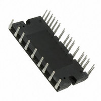
IGBT IPM MODULE 14A 600V 38SDIP
Manufacturer
STMicroelectronics
Type
IGBTr
Specifications of STGIPL14K60
Configuration
3 Phase
Current
14A
Voltage
600V
Voltage - Isolation
2500VDC
Package / Case
38-SDIP Module
Module Configuration
3-Phase Bridge
Transistor Polarity
N Channel
Dc Collector Current
15A
Collector Emitter Voltage Vces
600V
Power Dissipation Pd
44W
Operating Temperature Range
-40°C To
Rohs Compliant
Yes
Collector- Emitter Voltage Vceo Max
600 V
Collector-emitter Saturation Voltage
1.8 V
Continuous Collector Current At 25 C
14 A
Power Dissipation
35 W
Maximum Operating Temperature
+ 125 C
Minimum Operating Temperature
- 40 C
Mounting Style
Through Hole
Operating Temperature (max)
125C
Operating Temperature (min)
-40C
Pin Count
38
Mounting
Through Hole
Screening Level
Automotive
Lead Free Status / RoHS Status
Lead free / RoHS Compliant
Other names
497-10571-5
Available stocks
Company
Part Number
Manufacturer
Quantity
Price
Company:

Part Number:
STGIPL14K60
Manufacturer:
STMicroelectronics
Quantity:
120


STGIPL14K60
4
Smart shutdown function
The STGIPL14K60 integrates a comparator for fault sensing purposes. The comparator
non-inverting input (CIN) can be connected to an external shunt resistor in order to
implement a simple over-current protection function. When the comparator triggers, the
device is set in shutdown state and both its outputs are set to low-level leading the half-
bridge in 3-state. In the common overcurrent protection architectures the comparator output
is usually connected to the shutdown input through a RC network, in order to provide a
mono-stable circuit, which implements a protection time that follows the fault condition.
Our smart shutdown architecture allows to immediately turn-off the output gate driver in
case of overcurrent, the fault signal has a preferential path which directly switches off the
outputs. The time delay between the fault and the outputs turn-off is no more dependent on
the RC values of the external network connected to the shutdown pin. At the same time the
internal logic turns on the open-drain output and holds it on until the shutdown voltage goes
below the logic input lower threshold. Finally the smart shutdown function provides the
possibility to increase the real disable time without increasing the constant time of the
external RC network.
Figure 9.
Pls refer to
Table 12
Smart shutdown timing waveforms
the driver outputs are set in SD state
for internal propagation delay time details.
immediately after the comparator
triggering even if the SD signal
the lower input threshold
open drain gate
(internal)
has not yet reach
HVG/LVG
threshold
HIN/LIN
comp
SD/OD
upper
Fast shut down:
Vref
CP+
Doc ID 15589 Rev 5
CONTROLLER
FROM/TO
1
SHUT DOWN CIRCUIT
V
BIAS
R
C
SD
SD
SD/OD
PROTECTION
real disable time
R
TIME CONSTANTS
ON_OD
1
2
= (R
= R
SD
ON_OD
SMART
LOGIC
C
SD
SD
// R
2
Smart shutdown function
SD
)
C
SD
threshold
lower
15/22
Related parts for STGIPL14K60
Image
Part Number
Description
Manufacturer
Datasheet
Request
R

Part Number:
Description:
STMicroelectronics [RIPPLE-CARRY BINARY COUNTER/DIVIDERS]
Manufacturer:
STMicroelectronics
Datasheet:
Part Number:
Description:
STMicroelectronics [LIQUID-CRYSTAL DISPLAY DRIVERS]
Manufacturer:
STMicroelectronics
Datasheet:

Part Number:
Description:
BOARD EVAL FOR MEMS SENSORS
Manufacturer:
STMicroelectronics
Datasheet:
Part Number:
Description:
NPN TRANSISTOR POWER MODULE
Manufacturer:
STMicroelectronics
Datasheet:
Part Number:
Description:
TURBOSWITCH ULTRA-FAST HIGH VOLTAGE DIODE
Manufacturer:
STMicroelectronics
Datasheet:
Part Number:
Description:
Manufacturer:
STMicroelectronics
Datasheet:
Part Number:
Description:
DIODE / SCR MODULE
Manufacturer:
STMicroelectronics
Datasheet:
Part Number:
Description:
DIODE / SCR MODULE
Manufacturer:
STMicroelectronics
Datasheet:
Part Number:
Description:
Search -----> STE16N100
Manufacturer:
STMicroelectronics
Datasheet:
Part Number:
Description:
Search ---> STE53NA50
Manufacturer:
STMicroelectronics
Datasheet:
Part Number:
Description:
NPN Transistor Power Module
Manufacturer:
STMicroelectronics
Datasheet:
Part Number:
Description:
DIODE / SCR MODULE
Manufacturer:
STMicroelectronics
Datasheet: