CM75RX-24S Powerex Inc, CM75RX-24S Datasheet - Page 8
CM75RX-24S
Manufacturer Part Number
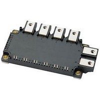
CM75RX-24S
Description
IGBT MOD 7PAC 1200V 75A NX SER
Manufacturer
Powerex Inc
Series
IGBTMOD™r
Type
7-PACr
Specifications of CM75RX-24S
Configuration
Three Phase Inverter with Brake
Voltage - Collector Emitter Breakdown (max)
1200V
Vce(on) (max) @ Vge, Ic
2.15V @ 15V, 75A
Current - Collector (ic) (max)
75A
Current - Collector Cutoff (max)
1mA
Input Capacitance (cies) @ Vce
7.5nF @ 10V
Power - Max
600W
Input
Standard
Ntc Thermistor
Yes
Mounting Type
Chassis Mount
Package / Case
Module
Module Configuration
Six
Dc Collector Current
75A
Collector Emitter Voltage Vces
1.2kV
Power Dissipation Pd
600W
Operating Temperature Range
-40°C To +150°C
Peak Reflow Compatible (260 C)
Yes
Rohs Compliant
Yes
Leaded Process Compatible
Yes
Prx Availability
RequestQuote
Distributorinventory
View
Voltage
1200V
Current
75A
Circuit Configuration
7-Pac
Recommended Gate Driver
M57159L
Recommended Dc To Dc Converter
VLA106-15242
Lead Free Status / RoHS Status
Lead free / RoHS Compliant
Igbt Type
-
Lead Free Status / RoHS Status
Lead free / RoHS Compliant
Other names
835-1119
Available stocks
Company
Part Number
Manufacturer
Quantity
Price
Company:

Part Number:
CM75RX-24S
Manufacturer:
MITSUBISHI
Quantity:
120
Company:
Part Number:
CM75RX-24S
Manufacturer:
Powerex Inc
Quantity:
135
Part Number:
CM75RX-24S
Manufacturer:
MIT
Quantity:
20 000


8
Powerex, Inc., 173 Pavilion Lane, Youngwood, Pennsylvania 15697 (724) 925-7272 www.pwrx.com
CM75RX-24S
Six IGBTMOD™ + Brake NX-S Series Module
75 Amperes/1200 Volts
10
10
10
10
10
10
-1
3
2
1
1
0
10
10
REVERSE RECOVERY SWITCHING LOSS VS.
REVERSE RECOVERY CHARACTERISTICS
0
0
V
V
R
T
Inductive Load
V
V
R
T
Inductive Load
j
j
CC
GE
G
CC
GE
G
= 150°C
= 150°C
= 13Ω
= 13Ω
FORWARD CURRENT, I
= 600V
= ±15V
= 600V
= ±15V
EMITTER CURRENT, I
(BRAKE PART - TYPICAL)
(BRAKE PART - TYPICAL)
EMITTER CURRENT
10
10
E
1
1
rr
E
F
, (AMPERES)
, (AMPERES)
I
t
rr
rr
10
10
2
2
10
10
10
10
10
10
-1
1
0
2
1
0
10
REVERSE RECOVERY SWITCHING LOSS VS.
10
1
0
V
V
I
T
Inductive Load
E
CC
GE
j
= 50A
= 150°C
COLLECTOR CURRENT, I
= 600V
= ±15V
(BRAKE PART - TYPICAL)
(BRAKE PART - TYPICAL)
COLLECTOR CURRENT
GATE RESISTANCE, R
SWITCHING LOSS VS.
GATE RESISTANCE
10
10
2
1
E
rr
C
, (AMPERES)
V
V
R
T
Inductive Load
G
j
CC
GE
G
, (Ω)
= 150°C
= 13Ω
= 600V
= ±15V
E
E
on
off
10
10
2
3
10
10
10
10
10
10
10
-1
-2
-3
2
1
0
0
10
10
1
-3
Single Pulse
T
Per Unit Base =
R
R
C
IMPEDANCE CHARACTERISTICS
th(j-c)
th(j-c)
0.35°C/W
(IGBT)
0.63°C/W
(Clamp Diode)
= 25°C
(BRAKE PART - TYPICAL)
(BRAKE PART - TYPICAL)
10
=
=
TRANSIENT THERMAL
GATE RESISTANCE, R
SWITCHING LOSS VS.
GATE RESISTANCE
-2
TIME, (s)
10
10
10
-1
-5
2
V
V
I
T
Inductive Load
C
G
j
CC
GE
, (Ω)
10
= 50A
= 150°C
10
= 600V
= ±15V
-4
0
E
E
on
off
10/10 Rev. 2
10
10
10
-3
3
1
10
10
10
-1
-2
-3
Related parts for CM75RX-24S
Image
Part Number
Description
Manufacturer
Datasheet
Request
R

Part Number:
Description:
IGBT MOD 7PAC 1200V 75A NX SER
Manufacturer:
Powerex Inc
Datasheet:

Part Number:
Description:
Manufacturer:
Powerex Inc
Datasheet:
Part Number:
Description:
Manufacturer:
Powerex Inc
Datasheet:
Part Number:
Description:
Manufacturer:
Powerex Inc
Datasheet:
Part Number:
Description:
Manufacturer:
Powerex Inc
Datasheet:
Part Number:
Description:
Manufacturer:
Powerex Inc
Datasheet:
Part Number:
Description:
Manufacturer:
Powerex Inc
Datasheet:
Part Number:
Description:
Manufacturer:
Powerex Inc
Datasheet:
Part Number:
Description:
Manufacturer:
Powerex Inc
Datasheet:
Part Number:
Description:
Manufacturer:
Powerex Inc
Datasheet:
Part Number:
Description:
Manufacturer:
Powerex Inc
Datasheet:
Part Number:
Description:
Manufacturer:
Powerex Inc
Datasheet:
Part Number:
Description:
Manufacturer:
Powerex Inc
Datasheet:
Part Number:
Description:
Manufacturer:
Powerex Inc
Datasheet: