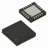
ATA5275-PGPI Atmel, ATA5275-PGPI Datasheet - Page 9

ATA5275-PGPI
Manufacturer Part Number
ATA5275-PGPI
Description
IC TRANSMITTER 125KHZ 20QFN
Manufacturer
Atmel
Datasheet
1.ATA5275-PGPI.pdf
(17 pages)
Specifications of ATA5275-PGPI
Rf Type
TPM
Frequency
125kHz
Package / Case
20-QFN
Lead Free Status / RoHS Status
Lead free / RoHS Compliant
Features
-
Other names
ATA5275-PGPITR
4.7.1
4.7.2
4739I–AUTO–01/06
Circuit Protection Cases
Error Diagnosis
The circuit protection is activated in normal mode, i.e., if the antenna circuit is driven to the oscil-
lation with its own frequency. It is switched off in standby mode. Between the end of the
transmission and the acknowledge signal the low side driver is switched on. In case a protection
switch-off occurs the half-bridge is set in tri-state mode.
For all cases, there is a filter implemented to debounce half-bridge switch-off for a time of T
(typically 20 µs). This debounce filter is activated in case the half-bridge is activated.
These are the following circuit protection cases:
During the transmission the diagnosis function of the IC supervises the antenna current and fre-
quency and the half-driver bridge supply voltage. If any error is detected at the end of the
transmission cycle the error indication is set (as in circuit protection case).
There are the following diagnosis cases:
1. Load dump protection: In case the voltage at DVCC exceeds a voltage VBAT
2. Overtemperature protection: In case the junction temperature exceeds a value of TSD
3.
1. Under-voltage detection: Monitors if DVCC is below VBAT
2. Antenna frequency error: Diagnosis if the oscillation frequency during transmission is
3. Antenna peak current error: Diagnosis if the peak current is greater than the adjusted
cally 31V).
(typically 165°C).
outside the typical tracking range 90 kHz to 160 kHz.
IA
PEAK
+ 15% typically.
UV
(typically 6.5V).
ATA5275
LD
(typi-
DEB
9


