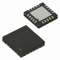
ATA5275-PGPI Atmel, ATA5275-PGPI Datasheet - Page 8

ATA5275-PGPI
Manufacturer Part Number
ATA5275-PGPI
Description
IC TRANSMITTER 125KHZ 20QFN
Manufacturer
Atmel
Datasheet
1.ATA5275-PGPI.pdf
(17 pages)
Specifications of ATA5275-PGPI
Rf Type
TPM
Frequency
125kHz
Package / Case
20-QFN
Lead Free Status / RoHS Status
Lead free / RoHS Compliant
Features
-
Other names
ATA5275-PGPITR
4.5.2
4.6
4.7
8
Coil Driver Output and Antenna Peak Current Control
Diagnosis and Protection
ATA5275
Resonance Tracking Mode
In case the antenna half-bridge is activated the VCO is tracked by the antenna current by means
of it zero crossing detection. The VCO runs at the antenna resonance frequency stationary. The
clock CLK
quality and resonance frequency (see section
an antenna current shunt resistor has to be applied to the SENSE pin. The shunt resistance is
used internally for the zero crossing detection of the antenna current only.
By this feature the antenna operates with the maximum voltage, current and field strength. It is
recommended specially for systems with high antenna Q-factors and low LC tolerances.
The driver circuit consists on a DMOS half-bridge designed for 1.5A peak current with low on-
resistance RDSON. It is short-circuit and overtemperature protected (see section
Protection” on page
a square wave voltage for the antenna RLC circuitry.
A very useful function of the driver stage is the build-in antenna current control loop. The IC
senses the current through the antenna internally and controls the peak value IA
ling the duty cycle DC
So the antenna can be designed for maximum antenna current with the typical or even the mini-
mum supply voltage. For higher supply voltages the current is controlled by reducing the driver
duty cycle. The reference value for the antenna current IA
resistor R
Note:
This feature allows the user to operate the IC in a wide field of operational voltage field and pro-
tects the driver stage and the antenna from antenna overcurrent.
The driver out square wave starts with a duty cycle of 50%. After tree or four cycles the duty
cycle can reach its maximum. As far as the peak current will stay smaller than IA
cycle maximum is really 100%. If during the ramp up of the antenna current the envelope of the
peak current will be greater than IA
driver output pulse to minimize the antenna current overshoot.
The IC supervises several parameters of IC operation for transmission diagnosis and circuit
protection.
In any case of circuit protection mode or error detection the IC indicates this states according to
the transmission protocol via the DIO line (see section
Signal” on page
IA
PEAK
Applying the formula above, the right driver current for the antenna has to be adjusted for the
worst supply voltage case. The IC operates from 14% up to 86% duty cycle for that case and
reduces the duty cycle for higher voltages (for the definition of the duty cycle DC
tion Hints” on page
=
CR
RT
750 mA
at the RCR pin.
deviates ±1.4% from the antenna resonance frequency, depending on the antenna
6).
8). The half-bridge is switched on by a low level signal at DIO and generates
DRV
50 k
-------------- -
R
CR
of the driver output.
14).
peak
+ 20% a pulse skipping function will suppress the next
“Application Hints” on page
“Transmission Acknowledge and Error
PEAK
can be adjusted externally with a
14). For that purpose,
DRV
PEAK
“Diagnosis and
4739I–AUTO–01/06
, see
peak
by control-
this duty
“Applica-


