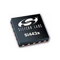
SI4430-B1-FM Silicon Laboratories Inc, SI4430-B1-FM Datasheet - Page 30

SI4430-B1-FM
Manufacturer Part Number
SI4430-B1-FM
Description
IC TXRX 900-960MHZ -8-13DB 20QFN
Manufacturer
Silicon Laboratories Inc
Specifications of SI4430-B1-FM
Package / Case
20-VQFN
Mfg Application Notes
Transitioning SI4430/31 to Rev B
Frequency
900MHz ~ 960MHz
Data Rate - Maximum
256kbps
Modulation Or Protocol
ISM
Applications
General Purpose
Power - Output
13dBm
Sensitivity
-121dBm
Voltage - Supply
1.8 V ~ 3.6 V
Current - Receiving
18.5mA
Current - Transmitting
30mA
Data Interface
PCB, Surface Mount
Antenna Connector
PCB, Surface Mount
Operating Temperature
-40°C ~ 85°C
Wireless Frequency
900 MHz to 960 MHz
Output Power
13 dBm
Operating Supply Voltage
1.8 V to 3.6 V
Maximum Operating Temperature
+ 85 C
Mounting Style
SMD/SMT
Maximum Supply Current
30 mA
Minimum Operating Temperature
- 40 C
Modulation
FSK, GFSK, OOK
Lead Free Status / RoHS Status
Lead free / RoHS Compliant
Memory Size
-
Lead Free Status / Rohs Status
Lead free / RoHS Compliant
Available stocks
Company
Part Number
Manufacturer
Quantity
Price
Company:
Part Number:
SI4430-B1-FM
Manufacturer:
Silicon Labs
Quantity:
135
Part Number:
SI4430-B1-FM
Manufacturer:
SILICON LABS/芯科
Quantity:
20 000
Si4430/31/32-B1
When AFC is enabled, the preamble length needs to be long enough to settle the AFC. In general, one byte of
preamble is sufficient to settle the AFC. Disabling the AFC allows the preamble to be shortened from 40 bits to 32
bits. Note that with the AFC disabled, the preamble length must still be long enough to settle the receiver and to
detect the preamble (see "6.7. Preamble Length" on page 47). The AFC corrects the detected frequency offset by
changing the frequency of the Fractional-N PLL. When the preamble is detected, the AFC will freeze for the
remainder of the packet. In multi-packet mode the AFC is reset at the end of every packet and will re-acquire the
frequency offset for the next packet. The AFC loop includes a bandwidth limiting mechanism improving the
rejection of out of band signals. When the AFC loop is enabled, its pull-in-range is determined by the bandwidth
limiter value (AFCLimiter) which is located in register 2Ah.
The AFC Limiter register is an unsigned register and its value can be obtained from the EZRadioPRO Register
Calculator spreadsheet.
The amount of error correction feedback to the Fractional-N PLL before the preamble is detected is controlled from
afcgearh[2:0]. The default value 000 relates to a feedback of 100% from the measured frequency error and is
advised for most applications. Every bit added will half the feedback but will require a longer preamble to settle.
The AFC operates as follows. The frequency error of the incoming signal is measured over a period of two bit
times, after which it corrects the local oscillator via the Fractional-N PLL. After this correction, some time is allowed
to settle the Fractional-N PLL to the new frequency before the next frequency error is measured. The duration of
the AFC cycle before the preamble is detected can be programmed with shwait[2:0]. It is advised to use the default
value 001, which sets the AFC cycle to 4 bit times (2 for measurement and 2 for settling). If shwait[2:0] is
programmed to 3'b000, there is no AFC correction output. It is advised to use the default value 001, which sets the
AFC cycle to 4 bit times (2 for measurement and 2 for settling).
The AFC correction value may be read from register 2Bh. The value read can be converted to kHz with the
following formula:
30
AFC_pull_in_range = ±AFCLimiter[7:0] x (hbsel+1) x 625 Hz
AFC disabled
AFC enabled
AFC Correction = 156.25Hz x (hbsel +1) x afc_corr[7: 0]
Freq Offset Register
AFC
Rev 1.1
RX
Frequency Correction
Freq Offset Register
Freq Offset Register
TX


