AC4790-200A-485 Laird Technologies, AC4790-200A-485 Datasheet - Page 22
AC4790-200A-485
Manufacturer Part Number
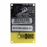
AC4790-200A-485
Description
TXRX 900MHZ 3.3-5.5V FHSS 200MW
Manufacturer
Laird Technologies
Series
AeroCommr
Specifications of AC4790-200A-485
Frequency
902MHz ~ 928MHz
Data Rate - Maximum
115.2kbps
Modulation Or Protocol
FHSS, FSK
Applications
AMR, Fire & Security Alarms, Telemetry
Power - Output
5mW ~ 200mW
Sensitivity
-110dBm
Voltage - Supply
3.3V, 5V
Current - Transmitting
68mA
Data Interface
Connector, 2 x 10 Header
Antenna Connector
On-Board, Chip
Operating Temperature
-40°C ~ 85°C
Package / Case
Module
Wireless Frequency
900 MHz
Interface Type
20-pin mini connector
Board Size
49 mm x 42 mm x 5 mm
Modulation
FHSS, FSK
Security
1 byte System ID, DES
Operating Voltage
3.3 V to 5.5 V
Output Power
200 mW
Antenna
Integral and External Dipole
Lead Free Status / RoHS Status
Contains lead / RoHS non-compliant
Memory Size
-
Current - Receiving
-
Lead Free Status / Rohs Status
Lead free / RoHS Compliant


1 8
S E R I A L I N T E R F A C E
should be a strong consideration when designing the system.
S Y S T E M T H R O U G H P U T
When operating as shown below, an AC4790 transceiver is capable of achieving the listed throughput. However, in
the presence of interference or at longer ranges, the transceiver may be unable to meet the specified throughput.
R A N D O M B A C K O F F
Random Back-Off – The transceivers utilize a Carrier Sense Multiple Access (CSMA) protocol with random back-off
and a selectable back-off seed. In the event of a collision, the transceiver will back off and retry the packet.
Specifically, when two transceivers detect a collision, each transceiver will choose a random number of packet times
that it will wait before retrying the packet. This random number is selected from a pool of numbers defined by the
back-off seed and consists of a number between 1 and 2, 1 and 4, 1 and 8, 1 and 16, 1 and 32, 1 and 64, 1 and 128
and 1 and 256. In a very dense network, where more than two transceivers could experience a collision, it is important
to have a higher random back-off seed.
E N G I N E E R ’ S T I P
In High-density applications, what amount of latency should be expected?
It is not easy to predict the exact amount of latency in high-density applications. There are
many variables that affect system latency. The three variables that most affect the latency are
the network load, the distance between transceivers, and whether the transceivers are
operating in a broadcast or addressed mode. There is no fixed answer as to how much latency
will be introduced in the system when considering high-density applications. In these cases we
can just offer qualitative analysis of the latency in high-density applications. As the network
load increases, then the number of collisions that will occur increases. As the number of
collisions increase, then the system latency increases. As the distance between the
transceivers increases, so to does the system latency. Finally, when transceivers operate in
addressed mode they will retry sending a packet up to the number of time specified in the
transmit retry parameter specified in the EEPROM. As the number of retries increases, the
system latency will increase also.
Radio not in continuous session
Radio continuously in session
RF Status
T a b l e 8 : M a x i m u m S y s t e m T h r o u g h p u t
Throughput (bps)
Half Duplex
25k
45k
Throughput (bps)
Full Duplex
each way
12.5k
22.5k
Related parts for AC4790-200A-485
Image
Part Number
Description
Manufacturer
Datasheet
Request
R

Part Number:
Description:
TXRX 900MHZ 3.3-5.5V FHSS 200MW
Manufacturer:
Laird Technologies
Datasheet:

Part Number:
Description:
TXRX 900MHZ 3.3V FHSS 1W
Manufacturer:
Laird Technologies
Datasheet:

Part Number:
Description:
TXRX 900MHZ 3.3-5.5V FHSS 200MW
Manufacturer:
Laird Technologies
Datasheet:
Part Number:
Description:
TXRX 900MHZ 3.3V FHSS 1W
Manufacturer:
Laird Technologies
Datasheet:

Part Number:
Description:
TXRX 900MHZ 3.3-5.5V FHSS 200MW
Manufacturer:
Laird Technologies
Datasheet:

Part Number:
Description:
Bluetooth Serial Module Development Kit
Manufacturer:
Laird Technologies
Part Number:
Description:
BLUETOOTH MODULE DEVELOPMENT KIT
Manufacturer:
Laird Technologies
Part Number:
Description:
Bluetooth 2.0 AT Data Module, Internal Antenna Development Kit
Manufacturer:
Laird Technologies

Part Number:
Description:
BLUETOOTH EVAL BOARD BTM511
Manufacturer:
Laird Technologies
Datasheet:

Part Number:
Description:
Bluetooth / 802.15.1 Modules & Development Tools BLUETTH Multimed MODLE, No ANT DEVKIT
Manufacturer:
Laird Technologies
Datasheet:

Part Number:
Description:
CHOKE COMMON MODE 110 OHMS SMD
Manufacturer:
Laird Technologies
Datasheet: