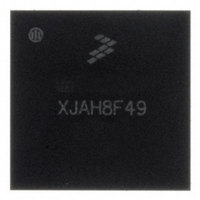
MC13224VR2 Freescale Semiconductor, MC13224VR2 Datasheet - Page 20

MC13224VR2
Manufacturer Part Number
MC13224VR2
Description
IC PLATFORM PIP802.15.4 145LGA
Manufacturer
Freescale Semiconductor
Datasheet
1.1322XUSB.pdf
(54 pages)
Specifications of MC13224VR2
Frequency
2.4GHz
Data Rate - Maximum
250kbps
Modulation Or Protocol
802.15.4 Zigbee
Applications
General Purpose
Power - Output
4dBm
Sensitivity
-100dBm
Voltage - Supply
2 V ~ 3.6 V
Current - Receiving
24mA
Current - Transmitting
29mA
Data Interface
PCB, Surface Mount
Memory Size
128kB Flash, 96kB RAM
Antenna Connector
PCB, Surface Mount
Operating Temperature
-40°C ~ 105°C
Package / Case
145-LGA
Lead Free Status / RoHS Status
Lead free / RoHS Compliant
Other names
MC13224VR2
MC13224VR2TR
MC13224VR2TR
Available stocks
Company
Part Number
Manufacturer
Quantity
Price
Company:
Part Number:
MC13224VR2
Manufacturer:
EPCOS
Quantity:
34 000
5.1
The parallel I/O features include:
5.2
The MC1322x designates 8 pins (KBI_0 to KBI_7) as a keyboard interface, where four of these signals
typically are outputs and four are inputs (KBI_4 to KBI_7) that support interrupts. These 8 pins could
typically be used as a matrix interface to support up to 16 switches or buttons, such as a keypad. These
signals can also be used as general purpose IO if a keyboard is not present.
During Hibernate or Doze, the KBI are unique in that they are kept alive. Four KBI are outputs and four
KBI are inputs. The inputs can be enabled as asynchronous interrupts to wake-up the MC1322x from the
sleep mode.
20
•
•
•
•
•
•
A total of 64 general-purpose I/O pins
Individual control (direction and output state) for each pin when in GPIO mode
Pad hysteresis enables
Software-controlled pull-ups/pull-downs on each input pin
When not used as GPIO, the IO provide alternative functions
— Debug ports for JTAG (four signals) and Nexus (fourteen signals) modules
— Four control signals for external RF components such as an LNA, PA, and antenna switch
— Eight analog inputs for ADC input channels
— Four signals for ADC reference voltages
— Eight signals for UART1 and UART2
— Two I
— Four timer block signals
— Four SPI block signals
— Four SSI block signals
— Eight KBI signals
Eight KBI pins are kept alive during Hibernate or Doze. Four KBI are output and four are inputs.
The input can be used as wake-up interrupts
Parallel IO (GPIO)
Keyboard Interface (KBI)
2
C signals
MC1322x Technical Data, Rev. 1.3
Freescale Semiconductor


