AC4490-200M Laird Technologies, AC4490-200M Datasheet - Page 38
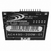
AC4490-200M
Manufacturer Part Number
AC4490-200M
Description
TXRX 900MHZ 3.3-5.5V TTL 200MW
Manufacturer
Laird Technologies
Series
AeroCommr
Specifications of AC4490-200M
Frequency
902MHz ~ 928MHz
Data Rate - Maximum
115.2kbps
Modulation Or Protocol
FHSS, FSK
Applications
AMR, Fire & Security Alarms, Telemetry
Power - Output
5mW ~ 200mW
Sensitivity
-110dBm
Voltage - Supply
3.3V, 5V
Current - Transmitting
68mA
Data Interface
Connector, 2 x 10 Header
Antenna Connector
MMCX
Operating Temperature
-40°C ~ 85°C
Package / Case
Module
Output Power
200 mW
Antenna
Integral and External Dipole
Lead Free Status / RoHS Status
Contains lead / RoHS non-compliant
Memory Size
-
Current - Receiving
-
Lead Free Status / Rohs Status
Lead free / RoHS Compliant
Other names
AC4490-200M-01


3 2
C O N F I G U R I N G T H E A C 4 4 9 0
C ha n g e S yn c C h a n n el
The OEM Host issues this command to change the sync channel byte
and enable sync to channel.
Note: Valid only for Server transceivers.
Sl ee p Wal k P o wer - Dow n
After the Host issues this command, the transceiver will de-assert its
In_Range line after entering power down. A Client in power down will
remain in sync with a Server for a minimum of 2 minutes. To maintain
syncronization with the Server, the Client should re-sync at least once
every 2 minutes. This is done by sending the Power Down wake up
command and waiting for the In_Range line to go active. Once this
occurs, the Client is in sync with the server and can be put back into
power-down mode.
Note: This command is valid only for Client transceivers.
S l ee p W al k P o w er - D ow n W a k e U p
The OEM Host issues this command to bring the transceiver out of
Power Down mode.
Note: This command is valid only for Client transceivers.
B ro ad c a st Pa ck e t s
The OEM Host issues this command to change the transceiver
operation between Addressed Packets and Broadcast Packets.
Addressed Packets are selected, the transceiver will send all packets to
the transceiver designated by the Destination Address programmed in
the transceiver. If Broadcast Packets are selected, the transceiver will
send its packets to all transceivers on that network. Setting bit-7 of API
Control to 1 can also enable Broadcast Packets.
W r i t e D e st i n at i o n Ad d r e s s
The OEM Host issues this command to the transceiver to change the
Destination Address.
Note: Only the three Least Significant Bytes of the MAC Address are
used for packet delivery.
If
Command: <0xCC> <0x05> <Channel>
Number of Bytes Returned: 3
Response: <0xCC> <Channel>
Parameter Range:
<Channel> = Sync Channel
Command: <0xCC> <0x06>
Number of Bytes Returned: 2
Response: <0xCC> <Channel>
Parameter Range:
<Channel> = RF Channel currently being used
Command: <0xCC> <0x07>
Number of Bytes Returned: 2
Response: <0xCC> <Channel>
Parameter Range:
<Channel> = RF Channel currently being used
Command: <0xCC> <0x08> <Mode>
Number of Bytes Returned: 2
Response: <0xCC> <Mode>
Parameter Range:
<Mode>
Command: <0xCC> <0x10> <MAC3> <MAC2> <MAC1>
Number of Bytes Returned: 4
Response: <0xCC> <MAC3> <MAC2> <MAC1>
Parameter Range:
<MAC>
destination MAC Address
= 0x00: Addressed
= 0x00 - 0xFF corresponding to 3 LSB’s of
0x01: Broadcast
Related parts for AC4490-200M
Image
Part Number
Description
Manufacturer
Datasheet
Request
R

Part Number:
Description:
TXRX 900MHZ 3.3-5.5V TTL 200MW
Manufacturer:
Laird Technologies
Datasheet:

Part Number:
Description:
TXRX 900MHZ 3.3V TTL 1W
Manufacturer:
Laird Technologies
Datasheet:

Part Number:
Description:
RF Modules & Development Tools USE 814-AC4490-200M
Manufacturer:
Laird Technologies
Part Number:
Description:
RF Modules & Development Tools USE 814-AC4490-200A
Manufacturer:
Laird Technologies

Part Number:
Description:
TXRX 900MHZ 3.3V TTL 1W
Manufacturer:
Laird Technologies
Datasheet:

Part Number:
Description:
TXRX 900MHZ 3.3-5.5V TTL 200MW
Manufacturer:
Laird Technologies
Datasheet:
Part Number:
Description:
TXRX 900MHZ 3.3-5.5V TTL 200MW
Manufacturer:
Laird Technologies
Datasheet:
Part Number:
Description:
RF Modules & Development Tools 5mW-200mW w/ int ant FOR AUSTRALIA
Manufacturer:
Laird Technologies
Part Number:
Description:
RF Modules & Development Tools 5mW-1000mW w/ant con FOR AUSTRALIA
Manufacturer:
Laird Technologies
Part Number:
Description:
WiFi / 802.11 Modules & Development Tools U 814-AC4490200A5485
Manufacturer:
Laird Technologies
Datasheet:
Part Number:
Description:
WiFi / 802.11 Modules & Development Tools U 814-AC4490200M5485
Manufacturer:
Laird Technologies

Part Number:
Description:
Bluetooth Serial Module Development Kit
Manufacturer:
Laird Technologies