MRF24J40MB-I/RM Microchip Technology, MRF24J40MB-I/RM Datasheet
MRF24J40MB-I/RM
Specifications of MRF24J40MB-I/RM
Available stocks


Related parts for MRF24J40MB-I/RM


MRF24J40MB-I/RM Summary of contents
Page 1
... Microchip Technology Inc. MRF24J40MB 2.4 GHz IEEE Std. 802.15.4™ 20 dBm RF Transceiver Module Preliminary Data Sheet DS70599B ...
Page 2
... REAL ICE, rfLAB, Select Mode, Total Endurance, TSHARC, UniWinDriver, WiperLock and ZENA are trademarks of Microchip Technology Incorporated in the U.S.A. and other countries. SQTP is a service mark of Microchip Technology Incorporated in the U.S.A. All other trademarks mentioned herein are property of their respective companies. ...
Page 3
... PIN DIAGRAM GND RESET WAKE SCK 2009 Microchip Technology Inc. MRF24J40MB RF/Analog Features: • ISM Band 2.405-2.475 GHz Operation • Data Rate: 250 kbps • -102 dBm Typical Sensitivity with -23 dBm Maximum Input Level • +20 dBm Typical Output Power with Power Control Range • ...
Page 4
... MRF24J40MB Table of Contents 1.0 Device Overview .......................................................................................................................................................................... 3 2.0 Circuit Description ........................................................................................................................................................................ 9 3.0 Regulatory Approval................................................................................................................................................................... 19 4.0 Electrical Characteristics ........................................................................................................................................................... 23 Appendix A: Revision History............................................................................................................................................................... 25 Index ................................................................................................................................................................................................... 27 The Microchip Web Site ....................................................................................................................................................................... 29 Customer Change Notification Service ................................................................................................................................................ 29 Customer Support ................................................................................................................................................................................ 29 Reader Response ................................................................................................................................................................................ 30 Product Identification System............................................................................................................................................................... 31 TO OUR VALUED CUSTOMERS It is our intention to provide our valued customers with the best documentation possible to ensure successful use of your Microchip products ...
Page 5
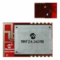
... DEVICE OVERVIEW The MRF24J40MB is a 2.4 GHz IEEE Std. 802.15.4™ compliant, surface mount module with integrated crystal, internal voltage regulator, matching circuitry, Power Amplifier, Low Noise Amplifier and PCB antenna. The MRF24J40MB module operates in the non-licensed 2.4 GHz frequency band. The integrated ...
Page 6
... No connection 10 V Power Power supply IN 11 GND Ground Ground 12 GND Ground Ground Legend: Pin type abbreviation Digital Input Output FIGURE 1-2: MICROCONTROLLER TO MRF24J40MB INTERFACE ® PIC MCU I/O SDO SDI SCK INTx I/O I/O DS70599B-page 4 Description MRF24J40MB CS SDI SDO SCK ...
Page 7
... PCB, and an area around the antenna, approximately 1.2", be kept clear of metal objects. A host PCB ground plane around the MRF24J40MB acts as a counterpoise to the PCB antenna recommended to extend the ground plane at least 0.4" around the module. ...
Page 8
... MRF24J40MB FIGURE 1-5: MOUNTING DETAILS Edge of PCB PCB Ground Plane (Counterpoise) Underneath and extend as far as possible to the sides and below the module (at least 0.4 inches on each side) for best performance DS70599B-page 6 Keep area around antenna (approximately 1.2 inches) 1.2” clear of metallic structures for best performance 0.315” ...
Page 9
... V1 V2 1.3.3 SLEEP detection (see To get the lowest power consumption from the (RSSI MRF24J40MB module during Sleep necessary to disable both the PA and LNA this, perform the following steps: 1. Configure the internal RF state machine to normal operation (TESTMODE (0x22F<2:0>) = 000). 2. Configure the GPIO2 and GPIO1 direction for output (TRISGP2 (0x34< ...
Page 10
... MRF24J40MB NOTES: DS70599B-page 8 Preliminary 2009 Microchip Technology Inc. ...
Page 11
... A schematic diagram of the module is shown in Figure 2-1 and the Bill of Materials (BOM) is shown in Table 2-1. The MRF24J40MB module is based on the Microchip Technology MRF24J40 IEEE 802.15.4™ 2.4 GHz RF Transceiver IC (U1). The serial I/O (SCK, SDI, SDO and CS), RESET, WAKE and INT pins are brought out to the module pins ...
Page 12
... MRF24J40MB FIGURE 2-1: MRF24J40MB SCHEMATIC DS70599B-page 10 Preliminary 2009 Microchip Technology Inc. ...
Page 13
... TABLE 2-1: MRF24J40MB BILL OF MATERIALS Designator Description C2 Chip Capacitor 0402 COG 0.5P C3 Chip Capacitor 0402 COG 0.5P C4 Chip Capacitor 0402 COG 1.0P C5 Chip Capacitor 0402 COG 1.5P C6 Not Used C7 Chip Capacitor 0402 COG 4.7P C8 Chip Capacitor 0402 COG 4.7P C9 Chip Capacitor 0402 COG 10P ...
Page 14
... MRF24J40MB TABLE 2-1: MRF24J40MB BILL OF MATERIALS (CONTINUED) Designator Description C46 Chip Capacitor 0402 X5R 100N C47 Chip Capacitor 0402 COG 47P C48 Chip Capacitor 0603 X5R 2.2U IC1 802.15.4 Radio IC2 Switch SPDT IC3 Power Amplifier IC4 Switch SPDT IC5 Low Noise Amplifier ...
Page 15
... Printed Circuit Board The MRF24J40MB module printed circuit board is con- structed with FR4 material, four 0.032 inches thick. The layers are shown in Figure 2-2 through Figure 2-6. The stack up of the PCB is shown in Figure 2-7. FIGURE 2-2: TOP SILK SCREEN ...
Page 16
... MRF24J40MB FIGURE 2-5: LAYER 3 – POWER PLANE Note: Top view positive Gerber. FIGURE 2-7: PCB LAYER STACK UP 0.032‚ +/- 0.005‚ DS70599B-page 14 FIGURE 2-6: Note: 1/2 oz. Copper 8 mil FR4 1/2 oz. Copper 12 mil FR4 1/2 oz. Copper 8 mil FR4 1/2 oz. Copper Preliminary BOTTOM COPPER Top view ...
Page 17
... Figure 2-13 shows the SWR simulation. The discrete matching circuitry matches the impedance of the antenna with the MRF24J40 transceiver IC. and HFSS™ 3D 22.0 6.0 3.8 1.54 5.3 0.85 1.2 2.0 1.0 1.0 0.72 Preliminary MRF24J40MB 1.3 4.2 3.82 6.6 4.3 1.0 9.6 0.5 1.2 6.6 1.0 DS70599B-page 15 ...
Page 18
... MRF24J40MB FIGURE 2-9: PCB ANTENNA SIMULATION DRAWING FIGURE 2-10: SIMULATED 2D RADIATION PATTERN DS70599B-page 16 Preliminary 2009 Microchip Technology Inc. ...
Page 19
... FIGURE 2-11: SIMULATED 3D RADIATION PATTERN FIGURE 2-12: SIMULATED PCB ANTENNA IMPEDANCE 2009 Microchip Technology Inc. MRF24J40MB Preliminary DS70599B-page 17 ...
Page 20
... MRF24J40MB FIGURE 2-13: SIMULATED PCB ANTENNA SWR DS70599B-page 18 Preliminary 2009 Microchip Technology Inc. ...
Page 21
... The MRF24J40MB module has received regulatory approvals for modular devices in the United States, Canada and European countries. Modular approval allows the end user to place the MRF24J40MB module inside a finished product and not require regulatory testing for an intentional radiator (RF transmitter), pro- vided no changes or modifications are made to the module circuitry. Changes or modifications could void the user’ ...
Page 22
... The antenna(s) used for this transmitter must not be co-located or operating in conjunction with any other antenna or transmitter. If the MRF24J40MB module is used in a portable application (antenna is less than 20 cm from persons during operation), the integrator is responsible for performing Specific Absorption Rate (SAR) testing in accordance with FCC rules 2 ...
Page 23
... Europe The MRF24J40MB module has been certified for use in European countries. The following testing has been completed: Test standard ETSI EN 300 328 V1.7.1 (2006-10): • Maximum Transmit Power • Maximum EIRP Spectral Density • Frequency Range • Radiated Emissions Test standards ETSI EN 301 489-1:2008 and ETSI EN 301 489-17:2008: • ...
Page 24
... MRF24J40MB NOTES: DS70599B-page 22 Preliminary 2009 Microchip Technology Inc. ...
Page 25
... Measured at Balun Matching Network Input at Frequency, 2.405-2.48 GHz Input Return Loss Noise Figure (including matching) Adjacent Channel @ +/-5 MHz Rejection Alternate Channel @ +/-10 MHz Rejection RSSI Range RSSI Error 2009 Microchip Technology Inc. MRF24J40MB Min Typ -40 — 2.4 — 2.4 3.3 0 — -0.3 — ...
Page 26
... MRF24J40MB TABLE 4-4: TRANSMITTER AC CHARACTERISTICS Typical values are 25° 3.3V, LO Frequency = 2.445 GHz A DD Parameters Condition RF Carrier Frequency Maximum RF Output Power RF Output Power Control Range TX Gain Control Programmed by Register Resolution Carrier Suppression TX Spectrum Mask for Offset Frequency > 3.5 MHz, O-QPSK Signal ...
Page 27
... APPENDIX A: REVISION HISTORY Revision A (June 2009) Original release of this document. Revision B (August 2009) Added Section 3.0 “Regulatory Approval”. 2009 Microchip Technology Inc. MRF24J40MB Preliminary DS70599B-page 25 ...
Page 28
... MRF24J40MB NOTES: DS70599B-page 26 Preliminary 2009 Microchip Technology Inc. ...
Page 29
... INDEX A AC Characteristics Receiver ......................................................................23 Transmitter .................................................................. 24 Antenna Impedance Simulated PCB ............................................................ 17 B Bill of Materials (BOM) ........................................................ 11 Block Diagrams Microcontroller to MRF24J40MB Interface.................... 4 MRF24J40MB ............................................................... 3 PA/LNA ......................................................................... 7 C Circuit Description ................................................................. 9 Customer Change Notification Service ............................... 28 Customer Notification Service ............................................. 28 Customer Support ............................................................... 28 D Details Module ..........................................................................5 Mounting ....................................................................... 6 Recommended PCB Footprint ...................................... 5 E Electrical Characteristics .....................................................23 Current Consumption ...
Page 30
... MRF24J40MB NOTES: DS70599B-page 28 Preliminary 2009 Microchip Technology Inc. ...
Page 31
... Local sales offices are also available to help customers. A listing of sales offices and locations is included in the back of this document. Technical support is available through the web site at: http://support.microchip.com Preliminary MRF24J40MB should contact their distributor, DS70599B-page 29 ...
Page 32
... Telephone: (_______) _________ - _________ Application (optional): Would you like a reply? Y Device: MRF24J40MB Questions: 1. What are the best features of this document? 2. How does this document meet your hardware and software development needs you find the organization of this document easy to follow? If not, why? 4 ...
Page 33
... M X Device Module Module Type Device MRF24J40MB; V range 2.4V to 3.6V DD Temperature Range I = -40C to +85C 2009 Microchip Technology Inc Examples: Tape and Temperature a) MRF24J40MB-I = Industrial temp. tray Reel Range b) MRF24J40MBT-I = Industrial temp., tape and reel. (Industrial) Preliminary MRF24J40MB . DS70599B-page 31 ...
Page 34
... Taiwan - Kaohsiung Tel: 886-7-536-4818 Fax: 886-7-536-4803 Taiwan - Taipei Tel: 886-2-2500-6610 Fax: 886-2-2508-0102 Thailand - Bangkok Tel: 66-2-694-1351 Fax: 66-2-694-1350 Preliminary 2009 Microchip Technology Inc. EUROPE Austria - Wels Tel: 43-7242-2244-39 Fax: 43-7242-2244-393 Denmark - Copenhagen Tel: 45-4450-2828 Fax: 45-4485-2829 France - Paris Tel: 33-1-69-53-63-20 ...