RDF1-433F RF Solutions, RDF1-433F Datasheet - Page 5
RDF1-433F
Manufacturer Part Number
RDF1-433F
Description
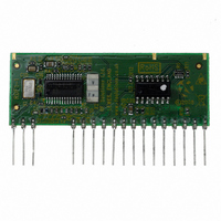
RECEIVER/DECODER 433MHZ RF
Manufacturer
RF Solutions
Datasheet
1.RDF1-433F.pdf
(8 pages)
Specifications of RDF1-433F
Frequency
433MHz
Modulation Or Protocol
FM, FSK
Data Interface
PCB, Through Hole
Antenna Connector
Through Hole
Voltage - Supply
5V
Operating Temperature
0°C ~ 70°C
Package / Case
20-SIP Module
Lead Free Status / RoHS Status
Lead free / RoHS Compliant
Features
-
Applications
-
Sensitivity
-
Memory Size
-
Data Rate - Maximum
-
Current - Receiving
-
Other names
RDF1
Available stocks
Company
Part Number
Manufacturer
Quantity
Price


DS RDF-1b March ‘09
Serial Data Output
The RDF1 has a serial data output. This outputs the serial number, button and battery
status of the transmitter encoder. This data may be fed directly to a microcontroller or
RS232 type driver circuit which may then be fed directly to a PC serial port.
Serial data is output initially and again every ½ second whilst data is being received from
the transmitter. i.e. this output is valid regardless of whether the Transmitter/Encoder has
been learnt to the RDF1 or not. The serial data packet contains a learn bit to show if an
encoder input is learnt.
Serial Data Format
Serial Data is sent every 1/2 second as a stream of 7 bytes at 9.6K baud. The serial data
format is: 8 data bits with 1 stop bit, no parity.
Serial data is output form the Decoder chip whenever a valid data packet from a
compatible RF Solutions transmitter/Encoder is received regardless of learn
Encoder Serial Number [NN]: made up of two 8-bit bytes where the most significant
byte is transmitted first.
This provides a total of 65,536 possible serial numbers.
Example:
Encoder Input Information [XX]: made up of two 8-bit bytes.
The high order byte is sent first representing inputs 16 down to 9 where the MSb is input
16 and the LSb is input 9.
The low order byte is sent next representing inputs 8 down to 1 where the MSb is input 8
and the LSb is input 1.
A bit at state 1 represents an encoder input as active.
Using this method inputs can be multiplexed giving maximum versatility.
Example:
N
12AB (hexadecimal) or 0001 0010 1010 1011 (binary)
00000000 00001000 - Shows input 4 active.
00000001 00000000 – Shows input 9 active
10000001 00000001 – Shows inputs 16, 9 and 1 active
N
RF R
©2008 REG No 277 4001, England.
X
X
ECEIVER
BAT $0D $0A
Output from Serial Data pin
D
7 bytes of data transmitted
ECODER
Line feed (last character)
Carriage return
Battery Status / Learn Status
Encoder Input information
Encoder serial number
Page 5
RDF1
Related parts for RDF1-433F
Image
Part Number
Description
Manufacturer
Datasheet
Request
R

Part Number:
Description:
FM Receiver And Decoder Module
Manufacturer:
RF Solutions
Datasheet:


Part Number:
Description:
RF Switch SPDT 0MHz to 2GHz 27dB 8-Pin SOIC T/R
Manufacturer:
M/A-Com Technology Solutions
Datasheet:
Part Number:
Description:
RF Switch SPST 500MHz to 2GHz 40dB 8-Pin SOIC T/R
Manufacturer:
M/A-Com Technology Solutions
Datasheet:

Part Number:
Description:
RF Switch SPDT 100MHz to 4GHz 14dB 6-Pin SOT-6
Manufacturer:
Skyworks Solutions Inc
Datasheet:
Part Number:
Description:
RF Switch SPST 500MHz to 2.5GHz 10dB 6-Pin SOT-6
Manufacturer:
Skyworks Solutions Inc
Part Number:
Description:
RF Amp Module Single Power Amp 1.91GHz 4.2V 10-Pin MCM
Manufacturer:
Skyworks Solutions Inc
Datasheet:
Part Number:
Description:
RF Amp Chip Single Power Amp 2.5GHz 4.5V 16-Pin QFN T/R
Manufacturer:
Skyworks Solutions Inc
Datasheet:

Part Number:
Description:
IC ENCODER TRANSMITTER RF 8DIP
Manufacturer:
RF Solutions
Datasheet:

Part Number:
Description:
IC DECODER RECEIVER RF 18DIP
Manufacturer:
RF Solutions
Datasheet:

Part Number:
Description:
IC ENCODER 3 DGTL I/O SOT23-6
Manufacturer:
RF Solutions
Datasheet:

Part Number:
Description:
IC ENCODER 3 DGTL I/O 8-PDIP
Manufacturer:
RF Solutions
Datasheet:

Part Number:
Description:
IC DECODER 3 DGTL I/O 8-PDIP
Manufacturer:
RF Solutions
Datasheet: