RDF1-433F RF Solutions, RDF1-433F Datasheet - Page 4
RDF1-433F
Manufacturer Part Number
RDF1-433F
Description
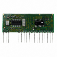
RECEIVER/DECODER 433MHZ RF
Manufacturer
RF Solutions
Datasheet
1.RDF1-433F.pdf
(8 pages)
Specifications of RDF1-433F
Frequency
433MHz
Modulation Or Protocol
FM, FSK
Data Interface
PCB, Through Hole
Antenna Connector
Through Hole
Voltage - Supply
5V
Operating Temperature
0°C ~ 70°C
Package / Case
20-SIP Module
Lead Free Status / RoHS Status
Lead free / RoHS Compliant
Features
-
Applications
-
Sensitivity
-
Memory Size
-
Data Rate - Maximum
-
Current - Receiving
-
Other names
RDF1
Available stocks
Company
Part Number
Manufacturer
Quantity
Price


DS RDF-1b March ‘09
Closed
Closed
Link1
Open
Open
System and Functional operation
Digital Data Outputs
Each RF Solutions transmitter contains a secure serial identity. When a switch is pressed,
the transmitter emits a unique secure RF signal. The Receiver can learn this signal and
allocate it to any of its output(s).
Any transmitter switch may be paired to one or many of a receiver’s outputs,
Many transmitters switches may be paired to a single receiver output.
This enables
The only limitation is that each receiver has a maximum capacity of 40 pairings, (can be
from the same or any number of transmitters).
Hint: the same transmitter may be taught to any number of receivers to create ‘master
keys’.
Learn: Learn Mode activation is achieved by pulling this input to GND briefly
Paring Procedure (Learning a Transmitter Switch to RDF1 digital output)
(as application circuit)
1. Select the receiver output to learn onto:
2. Operate the Transmitter button that you want to learn to the selected RDF1 output.
3. The Learn LED will then illuminate, operate the same transmitter button again.
4. The Learn LED will then flash to indicate learning is complete.
Erase Mode: Erase Mode is achieved by pulling this input to GND for >8 seconds. This
causes the internal EEPROM to be erased of all pre-learnt Transmitter pairings.
Digital Output Configuration: Momentary or Latching
These high impedance inputs are used to set the digital outputs to momentary or latched
actions
Outputs
Mom: This output is valid for the duration of valid key press of the transmitter switch
Latch: This output changes state on each valid transmitter switch press.
Outputs are digital CMOS/TTL (PIC Micro) with a series 220Ω protection resistor.
Outputs are all normally Low, active High. Each can sink/source 20/20mA.
Link Positions
One transmitter switch to control many receivers outputs, or,
Many transmitters switches to control one receiver output
a. Briefly operate the RDF1 Learn switch once
b. The Learn LED will flash once to indicate output 1 is selected
c. After the LED stops flashing, press the Learn switch again to select the next
d. Repeat step c until the required output is selected.
output channel.
Closed
Closed
Link2
Open
Open
RF R
©2008 REG No 277 4001, England.
ECEIVER
O/P 1
Latch
Mom
Mom
Mom
D
ECODER
O/P 2
Latch
Latch
Mom
Mom
Digital Outputs
Page 4
O/P 3
Latch
Latch
Latch
Mom
O/P 4
Latch
Latch
Latch
Mom
RDF1
Related parts for RDF1-433F
Image
Part Number
Description
Manufacturer
Datasheet
Request
R

Part Number:
Description:
FM Receiver And Decoder Module
Manufacturer:
RF Solutions
Datasheet:


Part Number:
Description:
RF Switch SPDT 0MHz to 2GHz 27dB 8-Pin SOIC T/R
Manufacturer:
M/A-Com Technology Solutions
Datasheet:
Part Number:
Description:
RF Switch SPST 500MHz to 2GHz 40dB 8-Pin SOIC T/R
Manufacturer:
M/A-Com Technology Solutions
Datasheet:

Part Number:
Description:
RF Switch SPDT 100MHz to 4GHz 14dB 6-Pin SOT-6
Manufacturer:
Skyworks Solutions Inc
Datasheet:
Part Number:
Description:
RF Switch SPST 500MHz to 2.5GHz 10dB 6-Pin SOT-6
Manufacturer:
Skyworks Solutions Inc
Part Number:
Description:
RF Amp Module Single Power Amp 1.91GHz 4.2V 10-Pin MCM
Manufacturer:
Skyworks Solutions Inc
Datasheet:
Part Number:
Description:
RF Amp Chip Single Power Amp 2.5GHz 4.5V 16-Pin QFN T/R
Manufacturer:
Skyworks Solutions Inc
Datasheet:

Part Number:
Description:
IC ENCODER TRANSMITTER RF 8DIP
Manufacturer:
RF Solutions
Datasheet:

Part Number:
Description:
IC DECODER RECEIVER RF 18DIP
Manufacturer:
RF Solutions
Datasheet:

Part Number:
Description:
IC ENCODER 3 DGTL I/O SOT23-6
Manufacturer:
RF Solutions
Datasheet:

Part Number:
Description:
IC ENCODER 3 DGTL I/O 8-PDIP
Manufacturer:
RF Solutions
Datasheet:

Part Number:
Description:
IC DECODER 3 DGTL I/O 8-PDIP
Manufacturer:
RF Solutions
Datasheet: