FCTN-WALL-433 Linx Technologies Inc, FCTN-WALL-433 Datasheet - Page 2
FCTN-WALL-433
Manufacturer Part Number
FCTN-WALL-433
Description
MODULE AC SWITCH RECEIVER 433MHZ
Manufacturer
Linx Technologies Inc
Datasheet
1.FCTN-WALL-433.pdf
(7 pages)
Specifications of FCTN-WALL-433
Function
Receiver, Relay
Modulation Or Protocol
ASK, OOK
Frequency
433MHz
Applications
General Remote Control, Wire Elimination
Interface
Receiver, Latched Output
Sensitivity
-95dBm
Data Rate - Maximum
1.2 kbps
Features
Switch 1,800W (15 Amps) or 1HP @ 120 VAC
Voltage - Supply
100 V ~ 120 VAC
Package / Case
Module
Board Size
104.1 mm x 56.6 mm x 64.3 mm
Minimum Operating Temperature
- 30 C
Product
RF Modules
Maximum Frequency
433.92 MHz
Supply Voltage (max)
110 V
Maximum Operating Temperature
+ 70 C
Lead Free Status / RoHS Status
Contains lead / RoHS non-compliant
Power - Output
-
Lead Free Status / Rohs Status
Lead free / RoHS Compliant
Other names
FCTN-WALL-433-1
FCTN-WALL-433-1
FCTN-WALL-433-1


Table 1: FCTN-WALL-*** Specifications
Notes
1. Characterized, but not tested.
2. Minumum relay load of any approved type
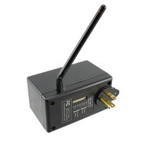
AC FUNCTION MODULE FEATURES
Figure 2: FCTN-WALL-*** Features
Page 2
ELECTRICAL SPECIFICATIONS
1. Up to 1,800 watts switched AC power outlet
2. Standard 3-prong plug can be used with wall outlet, power strip, or extension cord
3. Multi-position antenna for optimum reception
4. Control DIP Switches used to set address and command button
Parameter
POWER SECTION
Operating Voltage
Relay Rating
RECEIVER SECTION
Receive Frequency Range:
Center Frequency Accuracy
Receiver Sensitivity
Noise Bandwidth
ENVIRONMENTAL
Operating Temperature Range
Storage Temperature Range
Tungsten or Resistive load
Electronic Ballast
Power
Power
Power
Relay Cycle Life
FCTN-WALL-315
FCTN-WALL-418
FCTN-WALL-433
1
Designation
N
V
F
–
–
–
3dB
–
CC
C
Min.
-106
100
-50
-30
-45
3
–
–
–
–
–
–
–
–
–
–
–
Typical
433.92
1x10
-112
110
315
418
280
–
–
–
–
–
–
–
–
5
4
1,800
Max.
15.0
-118
120
+50
+50
+85
5.0
2
15
1
–
–
–
–
–
Units
VAC
MHz
MHz
MHz
dBm
FLA
kHz
kHz
mA
HP
°
°
W
A
A
C
C
Notes
–
2
1
1
1
1
1
–
–
–
–
–
1
1
1
THEORY OF OPERATION
SETTING MODULE ADDRESS
CREATING UNIQUE GROUPS
EQUIPMENT CONNECTION
The FCTN-WALL-*** module combines
the popular Linx LR Series receiver with a
decoder and high quality switching relay.
When transmitted data is received, the
data is presented to the decoder. The
decoder detects the logic states of the DIP
switch address lines, and if these match
the address settings of the encoder, the
decoder’s outputs are set to replicate the
state of the encoder’s inputs. In the AC
Function Module, the data lines are also
compared to the settings of four control dip
switches that determine which transmitter
buttons or data lines will be accepted. The
relationship is shown in the adjacent chart.
If the DIP switch labeled Button 1 is turned
on, then when data line D6 on the decoder
goes high, the AC Function Module will
activate and apply power to the output.
When line D7 goes high, the module will
turn off. As long as the other button
switches are turned off, the module will
ignore all of the other data lines. If multiple DIP switches are turned on, then the
module will be controlled by multiple buttons or data lines. For example, if
switches 1 and 2 are on, then lines D6 and D4 will switch the AC Function
Modules output on and lines D7 and D5 will turn it off.
The AC Function Module provides a total of sixteen unique address settings.
Address selection is made via the bottom four DIP switches on the module. In
order for the encoded commands sent by the transmitter to be recognized, the
address settings of the transmitter and receiver must match exactly.
The four control DIP switches can be used to create distinct groups of AC
Function Modules that can all be operated by a single command unit. For
example, any number of AC Function Modules can be set to a single address
and be controlled by one of the button pairs (ON / OFF) on a command unit. You
can also set up different banks using up to sixteen AC Function Modules, each
set to a different address. Please read the Contention Considerations section
when using multiple transmitters in close proximity.
Each AC Function Module is designed to switch AC loads of up to 1,800 watts.
Plug the AC Function Module in, then plug the equipment to be switched into the
receptacle on the face of the unit. More than one device can be connected with
the addition of a power strip; however, the total draw of all connected equipment
must never exceed the unit’s 1,800W rating.
Figure 3: Module DIP Switches
A0 = Addr. 1
A1 = Addr. 2
A2 = Addr. 3
A3 = Addr. 4
DIP Switch
Button 1
Button 2
Button 3
Button 4
Button
1
2
3
4
OFF ON
Off
D7
D5
D3
D1
Data Lines
On
D6
D4
D2
D0
Page 3
Related parts for FCTN-WALL-433
Image
Part Number
Description
Manufacturer
Datasheet
Request
R

Part Number:
Description:
MODULE 4 RELAY RECEIVER 418MHZ
Manufacturer:
Linx Technologies Inc
Datasheet:

Part Number:
Description:
MODULE 4 RELAY RECEIVER 433MHZ
Manufacturer:
Linx Technologies Inc
Datasheet:

Part Number:
Description:
MODULE 4 RELAY RECEIVER 315MHZ
Manufacturer:
Linx Technologies Inc
Datasheet:

Part Number:
Description:
MODULE AC SWITCH RECEIVER 315MHZ
Manufacturer:
Linx Technologies Inc
Datasheet:

Part Number:
Description:
MODULE AC SWITCH RECEIVER 418MHZ
Manufacturer:
Linx Technologies Inc
Datasheet:

Part Number:
Description:
MODULE 4 POS RECEIVER 418MHZ
Manufacturer:
Linx Technologies Inc
Datasheet:

Part Number:
Description:
MODULE RECEIVER DECODER 315MHZ
Manufacturer:
Linx Technologies Inc
Datasheet:
Part Number:
Description:
MODULE RECEIVER DECODER 418MHZ
Manufacturer:
Linx Technologies Inc
Datasheet:
Part Number:
Description:
MODULE RECEIVER DECODER 433MHZ
Manufacturer:
Linx Technologies Inc
Datasheet:

Part Number:
Description:
RF Modules & Development Tools 4 Relay Rcvr Mod 418MHzMomentry Outpt
Manufacturer:
Linx Technologies Inc
Datasheet:

Part Number:
Description:
MODULE USB LOW SPEED
Manufacturer:
Linx Technologies Inc
Datasheet:

Part Number:
Description:
IC TRANSCODER MT BI-DIR 20-SSOP
Manufacturer:
Linx Technologies Inc
Datasheet:

Part Number:
Description:
IC ENCODER LOW SECURITY 8DIP
Manufacturer:
Linx Technologies Inc
Datasheet:

Part Number:
Description:
IC DECODER MS SERIES 20-SSOP
Manufacturer:
Linx Technologies Inc
Datasheet:
Part Number:
Description:
IC ENCODER MS SERIES 20-SSOP
Manufacturer:
Linx Technologies Inc
Datasheet: