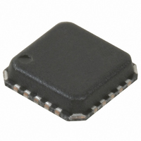
RF2483TR7 RFMD, RF2483TR7 Datasheet - Page 6

RF2483TR7
Manufacturer Part Number
RF2483TR7
Description
IC QUADRATURE MOD DUAL-BND 20QFN
Manufacturer
RFMD
Datasheet
1.RF2483PCK-410.pdf
(28 pages)
Specifications of RF2483TR7
Function
Modulator
Lo Frequency
700MHz ~ 2.2GHz
Rf Frequency
700MHz ~ 2.2GHz
P1db
6dBm
Noise Floor
-156.7dBm/Hz
Output Power
3dBm
Current - Supply
110mA
Voltage - Supply
2.7 V ~ 3.3 V
Test Frequency
1.9GHz
Package / Case
20-QFN
Lead Free Status / RoHS Status
Lead free / RoHS Compliant
Other names
689-1015-2
Available stocks
Company
Part Number
Manufacturer
Quantity
Price
Company:
Part Number:
RF2483TR7
Manufacturer:
M/A-COM
Quantity:
5 000
Part Number:
RF2483TR7
Manufacturer:
RF
Quantity:
20 000
RF2483
*=Not tested in production
6 of 28
I/Q Modulator High Band
(2400MHz)
Baseband Input Voltage*
Baseband Input Level
Baseband Input Impedance*
Input Bandwidth*
Sideband Suppression
Carrier Suppression
3rd Harmonic of Modulation
Suppression at FLO-3x100kHz
Baseband Inputs DC Current
Baseband Inputs AC Current
Variable Gain Amplifiers High
Band (2400MHz)
Gain Control Voltage Range
Gain Control Range
Gain Control Slope
Gain Control Input Impedance*
Output Power
Output Noise at FLO+20MHz*
Output P1dB*
Output IP3*
Drain*
Drain*
Parameter
7628 Thorndike Road, Greensboro, NC 27409-9421 · For sales or technical
support, contact RFMD at (+1) 336-678-5570 or sales-support@rfmd.com.
Min.
1.15
-10
-22
-39
50
30
30
38
40
30
30
22
50
50
50
50
32
26
16
-3
0
Specification
-156.7
Typ.
-155
150
+20
0.8
5.5
0.4
-35
1.2
-18
34
43
38
38
32
22
58
58
59
62
35
29
10
+6
37
47
-7
Max.
1.25
100
100
2.0
-14
-30
33
-3
3
dBm/Hz
dBm/Hz
Unit
dB/V
μA
dBm
dBm
MHz
dBc
dBc
dBc
dBc
dBc
dBc
dBc
dBc
dBc
dBc
dBc
dBc
V
kΩ
kΩ
μA
dB
dB
dB
dB
dB
V
V
PP
PP
V
FLO=0dBm, PLO=2400MHz, LO HB and RF
OUT HB ports are matched to 50Ω.
IQ=800mV
nals driven differentially and in quadrature
from a 50Ω source impedance. T
Common mode voltage
Measured differentially
Measured at 100kHz
I/Q source impedance 50Ω
GC=2.0V, no I/Q adjustment
GC=1.5V, no I/Q adjustment
GC=1.0V, no I/Q adjustment
GC=0.5V, no I/Q adjustment
GC=2.0V, no I/Q adjustment
GC=1.5V, no I/Q adjustment
GC=1.0V, no I/Q adjustment
GC=0.5V, no I/Q adjustment
GC=2.0V
GC=1.5V
GC=1.0V
GC=0.5V
V
FLO=0dBm, PLO=2400MHz, LO HB and RF
OUT HB ports are matched to 50Ω. Input IQ
signals driven differentially and in quadrature
from a 50Ω source impedance. T
Difference between output power at GC=2.0V
and GC=0.5V
Calculated GC=1.0V and 1.5V
GC=2.0V, IQ=800mV
GC=1.5V, IQ=800mV
GC=1.0V, IQ=800mV
GC=0.5V, IQ=800mV
GC=2.0V, IQ=800mV
GC=2.0V, IQ=0mV
GC=2.0V. Extrapolated from IM3 with two
baseband tones at 90kHz applied differen-
tially, in quadrature, at both I and Q inputs,
each tone 400mV
IQ at 100kHz
CC
CC
=2.7V, EN=2.7V, Bandsel=2.7V,
=2.7V, EN=2.7V, Bandsel=2.7V,
P-P
at 100kHz 1.2V
Condition
P-P
P-P
.
P-P
P-P
P-P
P-P
P-P
at 100kHz
at 100kHz
at 100kHz
at 100kHz
at 100kHz
Rev A9 DS080403
DC
. Input IQ sig-
A
A
=25
=25
o
o
C
C


