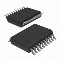
SA636DK/01,112 NXP Semiconductors, SA636DK/01,112 Datasheet - Page 13

SA636DK/01,112
Manufacturer Part Number
SA636DK/01,112
Description
IC MIXER FM IF SYSTEM LV 20-SSOP
Manufacturer
NXP Semiconductors
Series
SA636r
Datasheet
1.SA636DK01118.pdf
(17 pages)
Specifications of SA636DK/01,112
Package / Case
20-SSOP
Rf Type
Cellular, ASK, DECT, FSK, UHF, VHF
Frequency
500MHz
Number Of Mixers
2
Gain
11dB
Noise Figure
12dB
Secondary Attributes
Up Converter
Current - Supply
6.5mA
Voltage - Supply
2.7 V ~ 5.5 V
Mounting Style
SMD/SMT
Operating Supply Voltage
3V
Operating Temperature (min)
-40C
Operating Temperature (max)
85C
Operating Temperature Classification
Industrial
Lead Free Status / RoHS Status
Lead free / RoHS Compliant
Lead Free Status / RoHS Status
Lead free / RoHS Compliant, Lead free / RoHS Compliant
Other names
568-5046
935275292112
SA636DK/01
SA636DK/01,112
SA636DK/01
935275292112
SA636DK/01
SA636DK/01,112
SA636DK/01
4. Supply bypass and shielding: All of the inductors, the quad tank, and their shield must be grounded. A 0.1 F bypass capacitor on the supply
1. 10 dB S/N corresponds to BER = 10
1. RF generator: Set your RF generator at 110.592 MHz, use a 100 kHz modulation frequency and a 288 kHz deviation.
2. Layout: The layout is very critical in the performance of the receiver. We highly recommend our demo board layout.
3. RSSI: The smallest RSSI voltage (i.e., when no RF input is present and the input is terminated) is a measure of the quality of the layout and
Philips Semiconductors
Table 1.
RF frequency = 110.592 MHz; IF frequency = 9.8 MHz; RF level = –45 dBm; FM modulation = 100 kHz with 288 kHz peak deviation.
NOTE:
NOTES:
2003 Aug 01
Mixer/Osc section (ext LO = 160 mV
IF section
RF/IF section (internal LO)
SYMBOL
Low voltage high performance mixer FM
IF system with high-speed RSSI
design. If the lowest RSSI voltage is 500 mV or higher, it means the receiver is in regenerative mode. In that case, the receiver sensitivity
will be worse than expected.
pin improves sensitivity.
IIP3
PG
R
C
NF
IN
IN
DECT Application Circuit Electrical Characteristics
Conversion power gain
Noise Figure at 110 MHz
Third order input intercept
RF input resistance
RF input capacitance
IF amp gain
Limiter amp gain
Data level
3 dB data bandwidth
System RSSI output
System S/N
RF GENERATOR
110.592MHz
1
PARAMETER
LO / GENERATOR
120.392MHz
RMS
–3
.
)
Figure 11. SA636 Application Circuit Test Set Up
SCOPE
DC VOLTMETER
Matched f1 = 110.592 MHz; f2 = 110.892 MHz
13
TEST CONDITIONS
RF level = –10 dBm
RF level = –83 dBm
R
330
330
LOAD
SA636 DEMO BOARD
RSSI
= 3 k
load
load
SPECTRUM
ANALYZER
DATA
TYPICAL
V
–15
690
130
700
Product specification
3.6
1.4
13
12
38
54
10
CC
= 3V
SR00502
SA636
mV
UNITS
dBm
kHz
dB
dB
dB
dB
dB
pF
V
RMS


