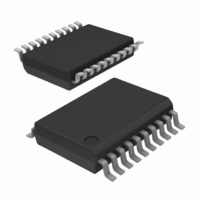
SA616DK/01,118 NXP Semiconductors, SA616DK/01,118 Datasheet - Page 5

SA616DK/01,118
Manufacturer Part Number
SA616DK/01,118
Description
IC MIXER FM IF SYSTEM LV 20-SSOP
Manufacturer
NXP Semiconductors
Series
SA616r
Datasheet
1.SA616DK01118.pdf
(31 pages)
Specifications of SA616DK/01,118
Package / Case
20-SSOP
Rf Type
Cellular, ASK, FSK
Frequency
150MHz
Number Of Mixers
2
Gain
17dB
Noise Figure
6.8dB
Secondary Attributes
RSSI Equipped
Current - Supply
3.5mA
Voltage - Supply
2.7 V ~ 7 V
Maximum Input Frequency
150 MHz
Mounting Style
SMD/SMT
Maximum Power Gain
17 dB
Operating Supply Voltage
3 V
Maximum Operating Temperature
+ 85 C
Minimum Operating Temperature
- 40 C
Operating Temperature (min)
-40C
Operating Temperature (max)
85C
Operating Temperature Classification
Industrial
Lead Free Status / RoHS Status
Lead free / RoHS Compliant
Lead Free Status / RoHS Status
Lead free / RoHS Compliant, Lead free / RoHS Compliant
Other names
568-2036-2
935275289118
SA616DK/01-T
935275289118
SA616DK/01-T
NXP Semiconductors
7. Functional description
SA616
Product data sheet
The SA616 is an IF signal processing system suitable for second IF systems with input
frequency as high as 150 MHz. The bandwidth of the IF amplifier and limiter is at least
2 MHz with 90 dB of gain. The gain/bandwidth distribution is optimized for 455 kHz,
1.5 kΩ source applications. The overall system is well-suited to battery operation as well
as high performance and high quality products of all types.
The input stage is a Gilbert cell mixer with oscillator. Typical mixer characteristics include
a noise figure of 6.2 dB, conversion gain of 17 dB, and input third-order intercept of
−9 dBm. The oscillator will operate in excess of 200 MHz in L/C tank configurations.
Hartley or Colpitts circuits can be used up to 100 MHz for crystal configurations. Butler
oscillators are recommended for crystal configurations up to 150 MHz.
The output impedance of the mixer is a 1.5 kΩ resistor permitting direct connection to a
455 kHz ceramic filter. The input resistance of the limiting IF amplifiers is also 1.5 kΩ. With
most 455 kHz ceramic filters and many crystal filters, no impedance matching network is
necessary. The IF amplifier has 43 dB of gain and 5.5 MHz bandwidth. The IF limiter has
60 dB of gain and 4.5 MHz bandwidth.
To achieve optimum linearity of the log signal strength indicator, there must be a 12 dBV
insertion loss between the first and second IF stages. If the IF filter or interstage network
does not cause 12 dBV insertion loss, a fixed or variable resistor or an L pad for
simultaneous loss and impedance matching can be added between the first IF output
(IF_AMP_OUT) and the interstage network. The overall gain will then be 90 dB with
2 MHz bandwidth.
The signal from the second limiting amplifier goes to a Gilbert cell quadrature detector.
One port of the Gilbert cell is internally driven by the IF. The other output of the IF is
AC-coupled to a tuned quadrature network. This signal, which now has a 90° phase
relationship to the internal signal, drives the other port of the multiplier cell.
The demodulated output of the quadrature drives an internal op amp. This op amp can be
configured as a unity gain buffer, or for simultaneous gain, filtering, and second-order
temperature compensation if needed. It can drive an AC load as low as 5 kΩ with a
rail-to-rail output.
A log signal strength completes the circuitry. The output range is greater than 90 dB and is
temperature compensated. This log signal strength indicator exceeds the criteria for
AMPS or TACS cellular telephone. This signal drives an internal op amp. The op amp is
capable of rail-to-rail output. It can be used for gain, filtering, or second-order temperature
compensation of the RSSI, if needed.
Remark: dBV = 20log V
All information provided in this document is subject to legal disclaimers.
Rev. 4 — 12 April 2011
O
/V
I
.
Low-voltage high performance mixer FM IF system
© NXP B.V. 2011. All rights reserved.
SA616
5 of 31


