AMMP-6120-BLK Avago Technologies US Inc., AMMP-6120-BLK Datasheet
AMMP-6120-BLK
Specifications of AMMP-6120-BLK
AMMP-6120-BLK
Q2313336
Available stocks


Related parts for AMMP-6120-BLK


AMMP-6120-BLK Summary of contents
Page 1
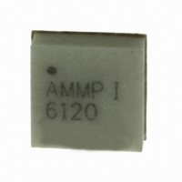
... AMMP-6120 8-24 GHz x2 Frequency Multiplier Data Sheet Description Avago Technologies’ AMMP-6120 is an easy-to-use in- tegrated frequency multiplier (x2 surface mount package designed for commercial communication systems. The MMIC takes GHz input signal and doubles GHz. It has integrated amplification, matching, harmonic suppression, and bias networks. The input/output are matched and fully DC blocked ...
Page 2
... Operating Channel Temp. Tstg Storage Case Temp. Tmax Maximum Assembly Temp.(60 sec. max.) Note: 1. Operation in excess of any one of these conditions may result in permanent damage to this device. AMMP-6120 DC Specifications/Physical Properties Symbol Parameters and Test Conditions Idq Drain Supply Current Ig Gate Current ...
Page 3
... AMMP-6120 Typical Performances = 50 :, Vd=5V, Vg=-1.4V 25°C out -10 -15 -20 -25 - Output Frequency (GHz) Figure 1. Output Power vs. Output Freq. @ Pin=+3dBm Output Frequency (GHz) Figure 3. Output Power [2H] vs. Output Freq. at variable Pin 0 -5 -10 -15 -20 -25 - Frequncy (GHz) Figure 5. Input and Output Return Loss ...
Page 4
Fout=8GHz Vg=-1.2V, Vd=4.5V 4 Vg=-1.2V, Vd=5.0V Vg=-1.4V, Vd=4.5V 2 Vg=-1.4V, Vd=5. Input Power [1H] (dBm) Figure 7. 2H Output Power Vs Input Power @ ...
Page 5
Fout=16GHz Vg=-1.2V, Vd=4.5V 4 Vg=-1.2V, Vd=5.0V Vg=-1.4V, Vd=4.5V 2 Vg=-1.4V, Vd=5. Input Power [1H] (dBm) Figure 13. 2H Output Power Vs Input Power @ ...
Page 6
... The AMMP-6120 is biased with a single positive drain supply Vdd and a single negative gate supply using separate bypass capacitors normally biased with the drain supply connected to Vd and the gate supply connected to Vg ...
Page 7
... Dimensions are in inches (mm) Recommended SMT Attachment The AMMP Packaged Devices are compatible with high volume surface mount PCB assembly processes. The PCB material and mounting pattern, as defined in the data sheet, optimizes RF performance and is strongly recommended. An electronic drawing of the land pattern is available from www ...
Page 8
Manual Assembly 1. Follow ESD precautions while handling packages. 2. Handling should be along the edges with tweezers. 3. Recommended attachment is conductive solder paste. Please see recommended solder reflow profile. Conduc- tive epoxy is not recommended. Hand soldering is ...
Page 9
... AMMP-6120 Part Number Ordering Information Part Number Devices Per Container AMMP-6120-BLK 10 AMMP-6120-TR1 100 AMMP-6120-TR2 500 Device Orientation (Top View) 4mm 12mm AMMP AMMP XXXX XXXX Carrier Tape and Pocket Dimensions For product information and a complete list of distributors, please go to our web site: Avago, Avago Technologies, and the A logo are trademarks of Avago Technologies in the United States and other countries. Data subject to change. Copyright © ...