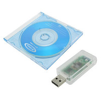
STEVAL-SPBT2ATV1 STMicroelectronics, STEVAL-SPBT2ATV1 Datasheet - Page 20

STEVAL-SPBT2ATV1
Manufacturer Part Number
STEVAL-SPBT2ATV1
Description
BOARD DEMO BLUETOOTH SPBT2532C2
Manufacturer
STMicroelectronics
Type
Bluetooth 2.0r
Specifications of STEVAL-SPBT2ATV1
Frequency
2.4GHz
Product
RF Modules
Supply Voltage (max)
6 V
Maximum Operating Temperature
+ 85 C
Supply Voltage (min)
4 V
For Use With/related Products
SPBT2532C2
Lead Free Status / RoHS Status
Lead free by exemption / RoHS compliant by exemption
Other names
497-10656
Application information
9.2
9.3
20/50
Antenna coupling
Despite of the type of antenna chosen, the connection between the RF out pin and the
antenna must be realized to get the maximum power transfer.
As a general rule the characteristic impedance (Z0)of the connection must be fixed at the
value of 50 Ω. The connection trace must be matched to respect such a condition.
50 Ω matching depends on various factors and elements that must be taken into
consideration:
●
●
●
Example of trace calculation
Example of strip-line calculation:
●
Tools for calculating the characteristic impedance, based on the physical and mechanical
characteristics of the PCB, can be easily found on the web.
Figure 13. Parameters for trace matching
Type of material, i.e. FR4 or others.
The electrical characteristics of the material, among them the electric constant,
2.4 GHz.
PCB and traces mechanical dimensions:
–
–
–
–
To get a strip-line of 50 Ω, using a 1 mm thick FR4 board, with an
with Cu thickness of 41 µm, the strip-line width must be 1.9 mm (Micro strip type
calculation).
PCB thickness
reference ground thickness
trace width
trace thickness
Doc ID 16089 Rev 7
ε
r = 4.3 at 2.4 GHz,
SPBT2532C2.AT
ε
r, at


