AD6655-125EBZ Analog Devices Inc, AD6655-125EBZ Datasheet - Page 30
AD6655-125EBZ
Manufacturer Part Number
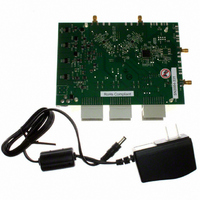
AD6655-125EBZ
Description
BOARD EVAL W/AD6655 & SOFTWARE
Manufacturer
Analog Devices Inc
Type
Receiver, CDMAr
Specifications of AD6655-125EBZ
Frequency
450MHz
Silicon Manufacturer
Analog Devices
Application Sub Type
IF Diversity Receiver
Kit Application Type
Communication & Networking
Silicon Core Number
AD6655
Kit Contents
Evaluation Board With AD6655 And Software
Lead Free Status / RoHS Status
Lead free / RoHS Compliant
For Use With/related Products
AD6655
Lead Free Status / Rohs Status
Compliant


AD6655
An on-board common-mode voltage reference is included in
the design and is available from the CML pin. Optimum perform-
ance is achieved when the common-mode voltage of the analog
input is set by the CML pin voltage (typically 0.55 × AVDD).
Differential Input Configurations
Optimum performance is achieved while driving the AD6655
in a differential input configuration. For baseband applications,
the AD8138, ADA4937-2, and
provide excellent performance and a flexible interface to the
ADC. The output common-mode voltage of the AD8138 is
easily set with the CML pin of the AD6655 (see Figure 47), and
the driver can be configured in a Sallen-Key filter topology to
provide band limiting of the input signal.
1V p-p
For baseband applications where SNR is a key parameter,
differential transformer coupling is the recommended input
configuration. An example is shown in Figure 48. To bias the
analog input, the CML voltage can be connected to the center
tap of the secondary winding of the transformer.
2V p-p
0.1µF
Figure 47. Differential Input Configuration Using the AD8138
Figure 48. Differential Transformer-Coupled Configuration
49.9Ω
49.9Ω
499Ω
523Ω
0.1µF
AD8138
499Ω
499Ω
ANALOG INPUT
ANALOG INPUT
2V p-p
ADA4938-2
R
R
R
R
C
C
0.1µF
C
P
D
A
0.1µF
0.1µF
R
differential drivers
Figure 50. Differential Input Configuration Using the AD8352
D
Figure 49. Differential Double Balun Input Configuration
0Ω
0Ω
VIN+
S
VIN–
AD6655
VIN+
VIN–
AD6655
R
S
G
16
1
2
3
4
5
CML
AVDD
CML
AD8352
P
V
Rev. 0 | Page 30 of 84
0.1µF
0.1µF
CC
14
8, 13
0.1µF
10
11
25Ω
25Ω
0.1µF
0.1µF
The signal characteristics must be considered when selecting
a transformer. Most RF transformers saturate at frequencies
below a few megahertz (MHz). Excessive signal power can also
cause core saturation, which leads to distortion.
At input frequencies in the second Nyquist zone and above, the
noise performance of most amplifiers is not adequate to achieve
the true SNR performance of the AD6655. For applications where
SNR is a key parameter, differential double balun coupling is
the recommended input configuration (see Figure 49).
An alternative to using a transformer-coupled input at
frequencies in the second Nyquist zone is to use the AD8352
differential driver is shown in Figure 50. See the
sheet for more information. In addition, if the application
requires an amplifier with variable gain, the
AD8376
performance driving the AD6655.
In any configuration, the value of the shunt capacitor, C, is
dependent on the input frequency and source impedance and
may need to be reduced or removed. Table 14 displays recom-
mended values to set the RC network. However, these values are
dependent on the input signal and should be used only as a
starting guide.
Table 14. Example RC Network
Frequency Range
(MHz)
0 to 70
70 to 200
200 to 300
>300
0.1µF
200Ω
200Ω
0.1µF
R
R
digital variable gain amplifiers (DVGAs) provide good
C
0.1µF
R
R
C
VIN+
VIN–
AD6655
VIN+
VIN–
AD6655
R Series
(Ω, Each)
33
33
15
15
CML
CML
AD8375
C Differential
(pF)
15
5
5
Open
AD8352
or
data
Related parts for AD6655-125EBZ
Image
Part Number
Description
Manufacturer
Datasheet
Request
R

Part Number:
Description:
BOARD EVAL FOR 150MSPS AD6655
Manufacturer:
Analog Devices Inc
Datasheet:

Part Number:
Description:
±1.7g Dual-Axis IMEMS Accelerometer Evaluation Board
Manufacturer:
Analog Devices Inc
Datasheet:

Part Number:
Description:
Inertial Sensor Evaluation System
Manufacturer:
Analog Devices Inc
Datasheet:
Part Number:
Description:
Manufacturer:
Analog Devices Inc
Datasheet:
Part Number:
Description:
Manufacturer:
Analog Devices Inc
Datasheet:
Part Number:
Description:
Manufacturer:
Analog Devices Inc
Datasheet:
Part Number:
Description:
Manufacturer:
Analog Devices Inc
Datasheet:
Part Number:
Description:
Manufacturer:
Analog Devices Inc
Datasheet:
Part Number:
Description:
Manufacturer:
Analog Devices Inc
Datasheet:
Part Number:
Description:
Manufacturer:
Analog Devices Inc
Datasheet:
Part Number:
Description:
Manufacturer:
Analog Devices Inc
Datasheet:
Part Number:
Description:
Manufacturer:
Analog Devices Inc
Datasheet:
Part Number:
Description:
Manufacturer:
Analog Devices Inc
Datasheet: