UPC8181TB-EVAL NEC, UPC8181TB-EVAL Datasheet - Page 2
UPC8181TB-EVAL
Manufacturer Part Number
UPC8181TB-EVAL
Description
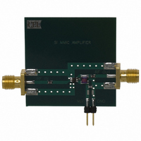
EVAL BOARD FOR UPC8181TB
Manufacturer
NEC
Type
Amplifier, MMICr
Datasheet
1.UPC8181TB-A.pdf
(8 pages)
Specifications of UPC8181TB-EVAL
Frequency
0Hz ~ 4GHz
For Use With/related Products
UPC8181TB
Lead Free Status / RoHS Status
Contains lead / RoHS non-compliant


ELECTRICAL CHARACTERISTICS
(T
TYPICAL PERFORMANCE CURVES
ABSOLUTE MAXIMUM RATINGS
Notes:
1. Operation in excess of any one of these conditions may result in
2. T
3. Mounted on a double-sided copper clad 50x50x1.6 mm epoxy
4. T
SYMBOLS
SYMBOLS
A
P
P
permanent damage.
glass PWB, T
= 25°C, V
RL
T
O(SAT)
RL
V
A
A
O(1dB)
P
I
P
T
CC
STG
CC
= 25°C, pins 4 and 6.
= +25 °C
IN
D
A
out
in
40
35
30
25
20
15
10
CIRCUIT CURRENT vs. SUPPLY VOLTAGE
5
0
CC
0
Supply Voltage
Total Cicuit Current
Power Dissipation
Operating Ambient
Temperature
Storage Temperature
Input Power
1 dB Gain Compression Output Level,
Saturated Output Power Level,
Input Return Loss,
Output Return Loss,
No Signal
= V
A
= +85°C.
OUT
PARAMETERS
Supply Voltage, V
1
= 3.0 V, Z
4
2
3
PARAMETERS AND CONDITIONS
S
2
= Z
L
= 50Ω)
PACKAGE OUTLINE
CC
PART NUMBER
UNITS
(V)
f = 0.9 GHz
f = 1.9 GHz
f = 2.4 GHz
f = 0.9 GHz, P
f = 1.9 GHz, P
f = 2.4 GHz, P
f = 0.9 GHz
f = 1.9 GHz
f = 2.4 GHz
f = 0.9 GHz
f = 1.9 GHz
f = 2.4 GHz
3
dBm
mW
mA
°C
°C
V
1
-55 to +150
4
RATINGS
-40 to +85
(cont.)
270
+10
(Unless otherwise specified, T
3.6
60
IN
IN
IN
= -5 dBm
= -5 dBm
= -5 dBm
RECOMMENDED
OPERATING CONDITIONS
Note:
1. Same voltage applied to pins 4 and 6
SYMBOLS
V
CC
A
40
35
30
25
20
15
10
= 25˚C)
5
0
-60
OPERATING AMBIENT TEMPERATURE
Operating Ambient Temperature, T
Supply Voltage
No Signal
V
CC
UNITS
PARAMETERS
-40
dBm
dBm
dB
dB
= 3.0 V
CIRCUIT CURRENT vs.
-20
0
1
+5.5
+4.5
+4.5
MIN
+20
4.5
7.5
8.0
6.0
7.0
9.0
–
–
–
+40
UNITS MIN
UPC8181TB
+60
V
+8.0
+7.0
+7.0
+9.5
+9.0
+9.0
TYP
10.5
11.0
10.0
12.0
S06
7.5
9.0
+80 +100
A
2.7
(°C)
TYP MAX
3.0
MAX
–
–
–
–
–
–
–
–
–
–
–
–
3.3
Related parts for UPC8181TB-EVAL
Image
Part Number
Description
Manufacturer
Datasheet
Request
R

Part Number:
Description:
RF Amplifier 3V Med Pwr Amplifier
Manufacturer:
NEC
Datasheet:
Part Number:
Description:
16/8 bit single-chip microcomputer
Manufacturer:
NEC
Datasheet:
Part Number:
Description:
Dual audio power amp circuit
Manufacturer:
NEC
Datasheet:
Part Number:
Description:
Dual comparator
Manufacturer:
NEC
Datasheet:
Part Number:
Description:
MOS type composite field effect transistor
Manufacturer:
NEC
Datasheet:
Part Number:
Description:
50 V/100 mA FET array incorporating 2 N-ch MOSFETs
Manufacturer:
NEC
Datasheet:
Part Number:
Description:
6-pin small MM high-frequency double transistor
Manufacturer:
NEC
Datasheet:
Part Number:
Description:
6-pin small MM high-frequency double transistor
Manufacturer:
NEC
Datasheet:
Part Number:
Description:
6-pin small MM high-frequency double transistor
Manufacturer:
NEC
Datasheet:
Part Number:
Description:
6-pin small MM high-frequency double transistor
Manufacturer:
NEC
Datasheet:
Part Number:
Description:
Twin transistors equipped with different model chips(6P small MM)
Manufacturer:
NEC
Datasheet: