ZIC2410USB-WNA-1 CEL, ZIC2410USB-WNA-1 Datasheet
ZIC2410USB-WNA-1
Specifications of ZIC2410USB-WNA-1


Related parts for ZIC2410USB-WNA-1


ZIC2410USB-WNA-1 Summary of contents
Page 1
... MeshConnect Family MeshConnect ISP / WNA (ZIC2410USB-WNA-1) 0007-05-08-06-001 User Guide (REV A) ...
Page 2
... ESH ONNECT ARDWARE ESCRIPTION ISP T I ARGET NTERFACE PROGRAMMING THE CEL MESHCONNECT ISP / WNA FIRMWARE REVISION HISTORY REV A C OMPUTER P ‐A ...
Page 3
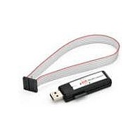
... The CEL MeshConnect ISP / WNA USB dongle (ZIC2410USB‐WNA‐1) coupled with the CEL Device‐ Programmer and CEL Packet Analyzer software tools can serve as all‐in‐one development tool with the ...
Page 4
... In order to use the MeshConnect ISP / WNA, the requirement exists to first install the Silicon Labs CP2102 USB drivers and the CEL software tools first. Do not connect the ISP / WNA dongle to the ...
Page 5
... USB port, self‐powered NOTE #1: Windows Vista is not supported. The CEL software tools have been made to work by operating them in Windows XP Compatibility Mode from within Windows Vista, however proper operation is not guaranteed. ...
Page 6
... MeshConnect ISP / WNA dongle to the computer prior to running the USB driver installation. The USB driver installation must be completed outside of the CEL software tools ...
Page 7
The License Agreement will be displayed as shown in Figure 4. Once you’ve read through and agreed to the agreement, click the Yes button. Figure 4: CP2101 USB Driver License Agreement 3. The Destination Location dialog will now be displayed as shown in Figure 5. Select the path to install the decompressed driver setup. The default is C:\Cygnal\CP2101 and will be used for this installation guide. Once the path has been selected, click the Next button. REV A Figure 5: CP2101 USB Driver Destination Path 0007‐05‐08‐06‐001 Page 7 of 22 ...
Page 8
While the driver is being decompressed, the decompression progress will be displayed by a dialog as shown in Figure 6. 5. Once the USB Driver has been decompressed successfully, the screen in Figure 7 will be displayed. Click the Finish button. Figure 7: CP2101 USB Driver Installation Complete ...
Page 9
Installing the USB Drivers 1. Start the installation of the USB drivers by executing the Setup.exe executable file located in the C:\Cygnal\CP2101\WIN\ directory (assuming the default path was used in Step 3). 2. The screen in Figure 8 will be displayed. Select the destination path by clicking the Browse button and navigating to the desired target directory. By default the C:\Program Files\Cygnal\CP2101 USB to UART Bridge Controller is selected, this guide will use the default path. Once the target path has been selected, click the Install button. ...
Page 10
... Once the USB Driver installation has completed, attach the CEL MeshConnect ISP / WNA USB dongle to the computer. The MeshConnect ISP / WNA is powered directly from the USB ...
Page 11
The dialog box in Figure 12 will appear. Select the Don’t search. I will choose the driver to install. option and press the Next button. Figure 12: CP2101 USB Driver Installation Options 4. The Cygnal USB Composite Device should be displayed in the Model window as shown in Figure 13 below. Click the Next button and dismiss any Windows Logo Testing dialogs by pressing the Continue Anyway button. Should the Cygnal USB Composite Device not be listed, click the Have Disk button and navigate to the target directory from Step 2 of the previous section (the default path is C:\Program Files\Cygnal\CP2101 USB to UART Bridge Controller). 5. The driver will begin to installation. Once installation has completed the dialog in Figure 14 will appear. Click the Finish button to dismiss the dialog. REV A Figure 13: CP2101 USB Driver Selection ...
Page 12
Figure 14: CP2101 USB Driver Installation Complete 6. The Found New Hardware Wizard dialog box will appear again, this time however it will be installing the driver for the CP2101 USB to UART Bridge Controller. Select the Install the software automatically (Recommended) and press the Next button. 7. The remaining drivers will automatically be installed. Dismiss any of the Windows Logo Testing dialogs ...
Page 13
... Make note of the assigned COM port as it will be needed when the CEL MeshConnect ISP / WNA USB dongle is used with the front‐end software. ...
Page 14
... For installation instructions for the CEL Device‐Programmer and CEL Packet‐Analyzer software tools, please refer to their respective User Guides found on the MeshConnect CD‐ROM or on the CEL website ...
Page 15
... Detailed instructions for using the front‐end software in conjunction with the CEL MeshConnect ISP / WNA USB dongle can be found in the software tool’s respective user guide. The user guides are located ...
Page 16
... This section details the connections between the MeshConnect ISP / WNA to the host PC (and the target board, for ISP functionality) for correct operation. Note that the CEL front‐end software and the USB ...
Page 17
... An additional slider switch becomes available REV A CEL MeshConnect WNA / ISP USB Dongle ISP CP210x MeshConnect ...
Page 18
MeshConnect IC). Table 1 and Table 2 detail the various statuses indicated by the LEDs and the functions of the various switches. Figure 19 and Figure 20 details the locations of the various switches and LEDs of the MeshConnect ISP / WNA. LABEL COLOR Active Amber ...
Page 19
... WNA Reset Figure 19: CEL MeshConnect ISP / WNA USB Dongle (Outside) WNA ISP Figure 20: CEL MeshConnect ISP / WNA USB Dongle (Inside) ISP Target Interface The target connection interface is configured to supply 3.0 Volts to the target and meant for direct ...
Page 20
REV A Figure 21: ISP Target Pinout 0007‐05‐08‐06‐001 Page 20 of 22 ...
Page 21
... Figure 22: CEL MeshConnect IC Target ISP Schematic REV A 0007‐05‐08‐06‐001 Page 21 of 22 ...
Page 22
... WNA software, SNAP software, or others). Firmware upgrading of the CEL MeshConnect ISP / WNA USB dongle should not be needed. Should CEL issue new firmware for the WNA the dongle may be re‐ ...