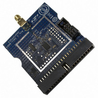
1000-TCB1C470 Silicon Laboratories Inc, 1000-TCB1C470 Datasheet

1000-TCB1C470
Specifications of 1000-TCB1C470
Related parts for 1000-TCB1C470
1000-TCB1C470 Summary of contents
Page 1
... Skip to "1.3. Code Development" on page 7. Demonstrate a wireless link between two nodes: 1. Get two Si1000/10 radio cards and two Software Development Boards. 2. Download bypass code to the Si1000/10's onboard MCU. 3. Configure the radio via the onboard LCD. 4. Skip to "1.4. Portable Demo Quick Start" on page 13. ...
Page 2
... The WDS GUI provides a convenient way to run configuration scripts and to change the radio settings bit-by-bit. 1. Install the WDS Chip Configurator either from the supplied CD or from www.silabs.com 2. Connect an Si10xx or Si101x RF card to the Si1000-MB motherboard. 3. Ensure jumpers/ switches are in the correct position: J16 ...
Page 3
... Note that the red LED, DS3, blinks when the LoadBoard Light firmware is running. 7. Launch the WDS Chip Configurator application on your PC (Start Silicon Laboratories WDS3) 8. WDS should automatically detect the Si1000 connected via USB. The following screen will appear: 9. Click Radio Control Panel and Select. ...
Page 4
... Si1000/10 QSG d. Select GFSK from Modulation Type. e. Select PN9 from Modulation Data. f. Click Update to write these values to the radio. 11. Connect a spectrum analyzer to the antenna output: You should see a GFSK-modulated test signal at 903 MHz. 12.Use the Register Setting panel to adjust the Transmit Power register: Close the Radio Control panel ...
Page 5
... Choose Register Setting Panel and Select. b. Scroll down to register 6D, the TX Power register. Set bits TXPOW[2: Click the W icon to write this register. Si1000/10 QSG Rev. 0.1 5 ...
Page 6
... Si1000/10 QSG c. Verify that the transmitter power has increased by checking the spectrum analyzer: 6 Rev. 0.1 ...
Page 7
... Install a C compiler. This example uses SDCC. A list of compiler links is at http://www.silabs.com/products/mcu/Pages/DevelopmentTools.aspx 3. Connect the USB Programming Adapter to your computer. 4. Plug a Si1000 915 MHz radio card in to the Software Development Board or Si1000-MB. 5. Connect power. 6. Connect the USB Programming Adapter ribbon cable the radio card. ...
Page 8
... Si1000/10 QSG 11. Ensure the Si1000 EVB is selected as a target: 8 Rev. 0.1 ...
Page 9
... MHz: Si1000/10 QSG Rev. 0.1 9 ...
Page 10
... Si1000/10 QSG 13.Fine-tune the EVB's crystal frequency. Scroll down to the RadioInit function and add a phyWrite command: 10 Rev. 0.1 ...
Page 11
... Press ctrl-shift-F7 to compile and build. b. Press the [DL] Icon to download. c. Ensure Download Successful appears in the Output Window. 15.Run: F5 Si1000/10 QSG Rev. 0.1 11 ...
Page 12
... Si1000/10 QSG 16.Connect spectrum analyzer to antenna port and verify modulated spectrum. 12 Rev. 0.1 ...
Page 13
... If the second receives it, it will reply with an ACKnlowledgement. The transmitting node will compute the packet error ratio (PER) as the ratio of packets sent and acknowledged to the total number of packets sent. 1. Connect the two Si1000 wireless MCU daughtercards to their respective software development boards. 2. Connect power to each. ...
Page 14
... Si1000/10 QSG 6. On page 2/4, select 2.4 kbps, GFSK, 903.0 MHz, and GO page 3/4, select output power +8 dBm and GO page 4/4, change ID: Destination to match the other card's ID: Self: Choose Packet length =5 and Max. Packets: 1000 Select GO Node 1: ...
Page 15
... AN415: EZRadioPRO® Programming Guide AN417: Si4x3x Family Crystal Oscillators Si1000/Si1010 MCU Example Code (included as part of the IDE installer) Lab testing and evaluation AN439: EZRadioPRO® RF Testing Quick-Start Guide AN437: Si4432 RF Performance and FCC Compliance Test Results ...
Page 16
... Install the Silicon Labs IDE software. Use the included CD or download from www.silabs.com. 2. Connect the USB Programming Adapter to your computer. 3. Plug the radio card in to the Software Development Board or Si1000-MB. 4. Connect power 5. Connect the USB Programming Adapter ribbon cable the radio card. ...


