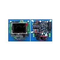
STEVAL-IHP001V3 STMicroelectronics, STEVAL-IHP001V3 Datasheet - Page 33

STEVAL-IHP001V3
Manufacturer Part Number
STEVAL-IHP001V3
Description
BOARD SMART PLUG STM32 SPZB260PR
Manufacturer
STMicroelectronics
Series
Zigbee™ SmartPlugr
Type
Microcontroller, Energy Meteringr
Specifications of STEVAL-IHP001V3
Frequency
2.4GHz
For Use With/related Products
STM32F10x, SPZB260-PRO, STPM01
Lead Free Status / RoHS Status
Lead free / RoHS Compliant
Other names
497-10677
STPM01
Figure 23. STPM01 data records map
8.19
DAP
DRP
DSP
DFP
DEV
DMV
CFL
CFH
msb
The first 6 registers are read-only except for the 8 bit mode signals in the DFP register (the
mode signals will be described later in this paragraph). The last two registers CFL and CFH
can be also written because they contain the configuration bits. Among these last 64 bits (32
of CFL and 32 of CFH), 8 bits are used for parity nibbles, then only 56 bits are used for
configuring and programming the STPM01.
Configuration bits
All the configuration bits that control the operation of the device (CFL and CFH data records)
can be written in a temporary or permanent way. In case of temporary writing the
configuration bits value are written in the so called shadow registers which are simple
latches that hold the configuration data. In case of permanent writing the configuration bits
are stored in the OTP (one time programmable) cells that keep the information for an
undefined period of time even if the STPM01 is without supply, but, once written, they
cannot be changed anymore.
The shadow registers are cleared whenever a reset condition occurs (both POR and remote
reset).
As indicated in the data records table, the configuration bits are 56. Each of them consists of
paired elements, one is latch, the OTP shadow, and another is the OTP antifuse element.
When the STPM01 is released in the market, all antifuses represents logic low state but they
can be written by the user in order to configure the STPM01.This means that STPM01 can
retain 56 bits of information even if it has been unsupplied for an undefined time. That’s why
the CFG signals are used to keep certain configuration and calibration values of device.
parity
parity
parity
parity
parity
parity
parity
parity
4 bit
1bit
p
p
uMOM
uRMS
11 bit
Doc ID 10853 Rev 7
type0 active energy
apparent energy
reactive energy
type 1 energy
20 bit
20 bit
upper part of configurators
lower part of configurators
iRMS
iMOM
16 bit
1bit 1bit
0
Theory of operation
1
mode signals
lower f(u)
Status
upper f(u)
8 bit
6 bit
lsb
33/60


