MICRF505DEV1 Micrel Inc, MICRF505DEV1 Datasheet - Page 26
MICRF505DEV1
Manufacturer Part Number
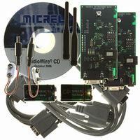
MICRF505DEV1
Description
KIT DEV RADIOWIRE 850-950MHZ
Manufacturer
Micrel Inc
Series
RadioWire®r
Type
Transceiver, ISMr
Specifications of MICRF505DEV1
Frequency
850MHz ~ 950MHz
For Use With/related Products
MICRF505
Lead Free Status / RoHS Status
Lead free / RoHS Compliant
Other names
576-1606
Available stocks
Company
Part Number
Manufacturer
Quantity
Price
Company:

Part Number:
MICRF505DEV1
Manufacturer:
Micrel Inc
Quantity:
135


Modulator
The
programmable
waveform is fed into a modulation varactor in the
VCO, which will create the desired frequency
modulation.
narrowed by increasing the rise-and fall times of the
waveform.
The modulator waveform is created by charging and
discharging a capacitor. A modulator clock controls
the timing, as shown in Figure19. For every rise-and
fall edge, 4 clock periods are being used. The
charging current during these 4 clock periods are not
equal, this is to reduce the high frequency
components in the waveform, which in turn will
narrow the frequency spectrum.
The frequency deviation can be set in three different
ways, as will be explained below. A formula for
setting the desired deviation is given at the end of
this chapter.
Modulator Clock
The modulator clock frequency is set by:
where f
Figure 19, f
Refclk_K is a 6 bit number and Mod_clkS is a 3 bit
number. Mod_clkS can be set to a value between 0
and 7. The modulator clock frequency should be set
according to the bit rate and shaping.
0000100
0000101
0000110
0000111
A6..A0
October 2006
Figure 19. Modulator Waveform and Clock
modulator
Modulator Clock
Modulator Waveform
MOD_CLK
f
BitRate_clkS1
MOD_CLK
Mod_F2
XCO
The
D7
-
-
is the modulator clock shown in
amplitude
is the crystal oscillator frequency
will
=
frequency spectrum
Refclk_K 2
BitRate_clkS0
create
Mod_clkS2
Mod_F1
D6
-
and
f
XCO
⋅
a
(7
−
frequency.
Mod_clkS
waveform
Mod_clkS1
RefClk_K5
Mod_F0
D5
‘0’
)
can
This
Mod_clkS0
with
RefClk_K4
Mod_I4
be
D4
‘1’
26
BitSync_clkS2
A f
corresponds to a signal filtered in a Gaussian filter
with a Bandwidth Period product (BT) of 1. When BT
is increased, the waveform will be less filtered.
Minimum BT is 1 (f
Figure 20 shows two waveforms with BT=1 and
BT=2, i.e. the f
the bit rate. When changing the BT factor, the
charge-and discharge times will also be changed,
and therefore the frequency deviation, as shown in
Figure 20.
Modulator Current
The current used during the rise- and fall times can
be programmed with the Mod_I4..Mod_I0 bit, the
last one being LSB. Figure 21 shows two waveforms
generated
higher frequency deviation and vice versa. The
effect of modulator clock and MOD_I is illustrated by:
To avoid saturation in the modulator it is important
not to exceed maximum Mod_I. Maximum Mod_I for
a given f
where INT() returns the integer part of the argument.
Mod
RefClk_K3
Mod_A3
Mod_I3
Figure 20. Two Different Modulator Clock Setting
MOD_CLK
D3
_
Mod_clkb > Mod_clka
Ia
MOD_CLK
of 8 times the bit rate (as in Figure 20)
>
MOD_I
with
Mod_clka
Mod_clkb
BitSync_clkS1
Mod
RefClk_K2
MOD_CLK
f
Mod_A2
Mod_I2
DEVIATION
is given by:
MAX
D2
two
_
=
MOD_CLK
Ib
INT(f
is 8 and 16 times higher than
. Higher current will give a
different
∝
MOD_CLK
BitSync_clkS0
RefClk_K1
f
is 8 times the bitrate).
MOD_I
Mod_A1
MOD_CLK
Mod_I1
D1
⋅
28 10 )-1
currents,
×
+1 408-944-0800
M9999-103106
-6
BitRate_clkS2
RefClk_K0
Mod_A0
Mod_I0
D0
where
Related parts for MICRF505DEV1
Image
Part Number
Description
Manufacturer
Datasheet
Request
R

Part Number:
Description:
Manufacturer:
Micrel Inc
Datasheet:
Part Number:
Description:
Manufacturer:
Micrel Inc
Datasheet:
Part Number:
Description:
Manufacturer:
Micrel Inc
Datasheet:
Part Number:
Description:
Manufacturer:
Micrel Inc
Datasheet:
Part Number:
Description:
Manufacturer:
Micrel Inc
Datasheet:
Part Number:
Description:
Manufacturer:
Micrel Inc
Datasheet:
Part Number:
Description:
Manufacturer:
Micrel Inc
Datasheet:
Part Number:
Description:
Manufacturer:
Micrel Inc
Datasheet:
Part Number:
Description:
Manufacturer:
Micrel Inc
Datasheet:
Part Number:
Description:
Manufacturer:
Micrel Inc
Datasheet:
Part Number:
Description:
Manufacturer:
Micrel Inc
Datasheet:
Part Number:
Description:
Manufacturer:
Micrel Inc
Datasheet:
Part Number:
Description:
Manufacturer:
Micrel Inc
Datasheet:
Part Number:
Description:
Manufacturer:
Micrel Inc
Datasheet: