101-1285 Rabbit Semiconductor, 101-1285 Datasheet - Page 27
101-1285
Manufacturer Part Number
101-1285
Description
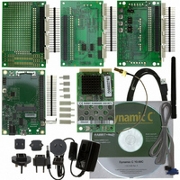
DEV KIT DELUXE MINICORE RCM5600W
Manufacturer
Rabbit Semiconductor
Series
MiniCore™r
Type
Transceiver, 802.11 b/gr
Datasheet
1.101-1285.pdf
(130 pages)
Specifications of 101-1285
Frequency
2.4GHz
Processor To Be Evaluated
Rabbit 5000
Processor Series
RCM5600W
Interface Type
RS-232, USB, PCI
Maximum Operating Temperature
+ 55 C
Minimum Operating Temperature
- 30 C
Operating Supply Voltage
3.15 V to 3.45 V
Silicon Manufacturer
Rabbit Semiconductor
Silicon Family Name
RabbitCore
Kit Contents
Board
Features
On-board Single-Chip 802.11b/g Transceiver, Built-In Web Server
Development Tool Type
Hardware /
Rohs Compliant
Yes
For Use With/related Products
RCM5600W
Lead Free Status / RoHS Status
Not applicable / Not applicable
Other names
316-1161


The Digital I/O accessory board may also be used to run the
SERIALTOSERIAL.C
Deluxe Development Kit.
To install the Digital I/O accessory board, insert the strip of header pins included with the
accessory board into the socket at J12 on the bottom side of the Digital I/O accessory
board. Then line up the Digital I/O accessory board with the Interface Board standoffs/
connectors and install the Digital I/O accessory board pins into socket J2 on the Interface
Board. Secure the Digital I/O accessory board with the long plastic standoffs/connectors
from above as shown in Figure 6—note that one plastic standoff/connector needs to be
inserted “upside down” to secure the Digital I/O accessory board to the antenna bracket.
Pins 1–2, 3–4, 5–6, and 7–8 on headers JP5 and JP8 on the Digital I/O accessory board
must be jumpered. Pins 2–4 and 3–5 on header JP7 on the Digital I/O accessory board
must also be jumpered.
Uncomment the following line in the sample programs when you are using the Digital I/O
accessory board.
•
OEM User’s Manual
TOGGLESWITCH.C
sory board and lights LEDs DS1–DS4 when the corresponding pushbutton switch is
pressed. LEDs DS1–DS2 on the Digital I/O accessory board are controlled by PA4–
PA7, and switches S1–S4 are controlled by PB4–PB7 respectively.
#define DIGITAL_IO_ACCESSORY
—monitors switches S1, S2, S3, and S4 on the Digital I/O acces-
sample programs. This accessory board is included only with the
Figure 6. Install Digital I/O Accessory Board
TOGGLESWITCH.C
and the
21
Related parts for 101-1285
Image
Part Number
Description
Manufacturer
Datasheet
Request
R

Part Number:
Description:
COMPUTER SNGLBD BL2120 FRCTNLOCK
Manufacturer:
Rabbit Semiconductor
Datasheet:

Part Number:
Description:
KIT APPLCTN RABBITCORE RCM4010
Manufacturer:
Rabbit Semiconductor
Datasheet:

Part Number:
Description:
KIT MESH NETWORK ADD-ON RCM4510W
Manufacturer:
Rabbit Semiconductor
Datasheet:

Part Number:
Description:
KIT DEV FOR BL2500 COYOTE
Manufacturer:
Rabbit Semiconductor
Datasheet:

Part Number:
Description:
KIT APPLICATION SIMPLE SENSOR
Manufacturer:
Rabbit Semiconductor
Datasheet:

Part Number:
Description:
KIT DEV RCM5400W US/INTERNATIONL
Manufacturer:
Rabbit Semiconductor
Datasheet:


Part Number:
Description:
KIT FOR BL4S100 STARTER PACKAGE
Manufacturer:
Rabbit Semiconductor
Datasheet:

Part Number:
Description:
DEV KIT STANDARD MINI RCM5600W
Manufacturer:
Rabbit Semiconductor
Datasheet:

Part Number:
Description:
MODULE RABBITCORE RCM3720
Manufacturer:
Rabbit Semiconductor
Datasheet:
Part Number:
Description:
MODULE RABBITCORE RCM3220
Manufacturer:
Rabbit Semiconductor
Datasheet:
Part Number:
Description:
MODULE RABBITCORE RCM3210
Manufacturer:
Rabbit Semiconductor
Datasheet:
Part Number:
Description:
COMPUTER SGL-BOARD OP6600 W/SRAM
Manufacturer:
Rabbit Semiconductor
Datasheet:
Part Number:
Description:
COMPUTER SGL-BD BL2000 SRAM/FLSH
Manufacturer:
Rabbit Semiconductor