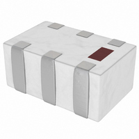
2450DP15E5400E Johanson Technology Inc, 2450DP15E5400E Datasheet - Page 56

2450DP15E5400E
Manufacturer Part Number
2450DP15E5400E
Description
DIPLEXER LPF/BPF 2.45/5.4GHZ
Manufacturer
Johanson Technology Inc
Specifications of 2450DP15E5400E
Frequency Bands (low / High)
2.4GHz ~ 2.5GHz / 4.9GHz ~ 5.9GHz
Low Band Attenuation (min / Max Db)
20.00dB / 0.70dB
High Band Attenuation (min / Max Db)
17.00dB / 1.60dB
Return Loss (low Band / High Band)
9.5dB / 9.5dB
Mounting Type
Surface Mount
Package / Case
1206 (3216 Metric)
Return Loss
9.5dB
Bandpass Insertion Loss Max
1.6dB
Attenuation @ Reject Band Min
17dB
Termination Type
SMD
Rohs Compliant
Yes
Capacitance
0µF
Lead Free Status / RoHS Status
Lead free by exemption / RoHS Compliant
Other names
2450DP15E5400
2450DP15E5400
2450DP15E5400
56
T
The following technical notes are available for viewing on our website at
www.johansontechnology.com/technicalnotes/
G
RF C
RF C
ECHNICAL
ENERAL
•
•
•
•
•
•
•
•
•
•
•
•
•
•
•
•
•
•
APACITORS AND
OMPONENTS
RoHS Compliance
Storage and Solderability Checklist
Q & ESR Explained
SRF & PRF for RF Capacitors
Measuring S-Parameters of High-Q Caps
S-Parameter Accuracy
Capacitor Mounting & S-Parameters
Capacitor RF Current & Power
Trimming Characteristics of LASERtrim® Chip Caps
Dishal Bandpass Filter Tuning Using LASERtrim® Chip Caps
Reference Oscillator Tuning Using LASERtrim® Chip Caps
High Frequency Inductor Modeling Utilizing MLISoft®
Soldering Requirements for Chip Capacitor, Chip Inductor, and Wirewound Inductor
Chip Antenna Layout Considerations for 802.11 Applications
Chip Balun: Defi nitions & Measurement Methodology
RF Antenna Tape & Reel Packaging
RF Component Tape & Reel Packaging
Soldering requirements for RFCC
N
OTES
I
NDUCTORS
www.johansontechnology.com


