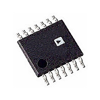
AD8302ARU-REEL Analog Devices Inc, AD8302ARU-REEL Datasheet - Page 19

AD8302ARU-REEL
Manufacturer Part Number
AD8302ARU-REEL
Description
IC DETECTOR RF/IF 14-TSSOP T/R
Manufacturer
Analog Devices Inc
Datasheet
1.AD8302ARUZ.pdf
(24 pages)
Specifications of AD8302ARU-REEL
Rohs Status
RoHS non-compliant
Frequency
2.7GHz
Rf Type
General Purpose
Input Range
-60dBm ~ 0dBm
Accuracy
0.5dB
Voltage - Supply
2.7 V ~ 5.5 V
Current - Supply
23mA
Package / Case
14-TSSOP (0.173", 4.40mm Width)
Pin Count
14
Screening Level
Industrial
Package Type
TSSOP
Lead Free Status / Rohs Status
Not Compliant
Available stocks
Company
Part Number
Manufacturer
Quantity
Price
Part Number:
AD8302ARU-REEL7
Manufacturer:
ADI/亚德诺
Quantity:
20 000
REV. A
The comparator mode can be turned into a controller mode by
closing the loop around the VMAG and VPHS outputs.
Figure 11 illustrates a closed loop controller that stabilizes the gain
and phase of a DUT with gain and phase adjustment elements.
If VMAG and VPHS are properly conditioned to drive gain and
phase adjustment blocks preceding the DUT, the actual gain and
phase of the DUT will be forced toward the prescribed setpoint
gain and phase given in Equations 11 and 12. These are essentially
AGC and APC loops. Note that as with all control loops of this kind,
loop dynamics and appropriate interfaces all must be considered
in more detail.
Figure 11. By Applying Overall Feedback to a DUT Via
External Gain and Phase Adjusters, the AD8302 Acts
as a Controller
APPLICATIONS
Measuring Amplifier Gain and Compression
The most fundamental application of AD8302 is the monitoring
of the gain and phase response of a functional circuit block such as
an amplifier or a mixer. As illustrated in Figure 12, directional
couplers, DC
the “Black Box” DUT. The attenuators ensure that the signal
levels presented to the AD8302 fall within its dynamic range.
From the discussion in the Dynamic Range section, the optimal
choice places both channels at P
which corresponds to –43 dBV. To achieve this, the combination
of coupling factor and attenuation are given by:
where C
attenuation factors, and GAIN
identical couplers are used for both ports, then the difference in the
two attenuators compensates for the nominal DUT gain. When the
actual gain is nominal, the VMAG output is 900 mV, corresponding
to 0 dB. Variations from nominal gain appear as a deviation from
900 mV or 0 dB with a 30 mV/dB scaling. Depending on the nominal
insertion phase associated with DUT, the phase measurement may
require a fixed phase shift in series with one of the channels to bring
the nominal phase difference presented to the AD8302 near the
optimal 90° point.
C
C
B
A
B
+
+
and C
L
L
B
A
MAG
B
=
=
and DC
A
P
P
IN
are the coupling coefficients, L
IN
−
+
P
GAIN
A
OPT
, sample the input and output signals of
NOM
OPT
INPA
INPB
NOM
AD8302
−
= –30 dBm referenced to 50 Ω,
is the nominal DUT gain. If
P
OPT
VMAG
MSET
PSET
VPHS
B
and L
MAG
SETPOINT
PHASE
SETPOINT
A
are the
(15)
(16)
–19–
When the insertion phase is nominal, the VPHS output is 900 mV.
Deviations from the nominal are reported with a 10 mV/degree
scaling. Table I gives suggested component values for the
measurement of an amplifier with a nominal gain of 10 dB and
an input power of –10 dBm.
Figure 12. Using the AD8302 to Measure the Gain and
Insertion Phase of an Amplifier or Mixer
Table I. Component Values for Measuring a 10 dB Amplifier
with an Input Power of –10 dBm
Component
R1, R2
R5, R6
C1, C4, C5, C6
C2, C8
C3
C7
AttenA
AttenB
DC
The gain measurement application can also monitor gain and
phase distortion in the form of AM-AM (gain compression) and
AM-PM conversion. In this case, the nominal gain and phase
corresponds to those at low input signal levels. As the input level
is increased, output compression and excess phase shifts are
measured as deviations from the low level case. Note that the signal
levels over which the input is swept must remain within the dynamic
range of the AD8302 for proper operation.
A
, DC
“BLACK BOX”
B
DC
DC
A
B
R1
R2
C1
C4
C6
C5
C3
R4
VP
Value
52.3 Ω
100 Ω
0.001 µF
Open
100 pF
0.1 µF
10 dB (See Text)
1 dB (See Text)
20 dB
ATTEN
ATTEN
C7
1
2
3
4
5
6
7
COMM
INPA
OFSA
VPOS
OFSB
INPB
COMM
A
B
AD8302
VMAG
MSET
VPHS
MFLT
VREF
PSET
PFLT
14
13
12
11
10
9
8
AD8302
C2
C8
Quantity
2
2
4
1
1
1
1
2
R5
R6
H
H


