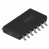
NJM2211M NJR, NJM2211M Datasheet - Page 9

NJM2211M
Manufacturer Part Number
NJM2211M
Description
IC FSK DEMOD/ TONE DECODER S014
Manufacturer
NJR
Datasheet
1.NJM2211D.pdf
(10 pages)
Specifications of NJM2211M
Function
Demodulator
Current - Supply
11mA
Voltage - Supply
4.5 V ~ 20 V
Package / Case
14-DMP
Lead Free Status / RoHS Status
Contains lead / RoHS non-compliant
Gain
-
Noise Figure
-
P1db
-
Lo Frequency
-
Rf Frequency
-
Available stocks
Company
Part Number
Manufacturer
Quantity
Price
Company:
Part Number:
NJM2211M-TE1
Manufacturer:
NJR
Quantity:
12 000
Design Instructions
components : R0, R1, C0, C1, and C
1. Chose R0 to be in the range of 15kΩ to 100kΩ. This choice is arbitrary.
2. Calculate C0 to set center frequency, f
3. Calculate R1 to set bandwidth ±∆f (see Design Equation No.5) : R1=R0 (f
Note : The total detection bandwidth covers the frequency range of f
4. Calculate value of C1 for a given loop damping factor :
5. Calculate value of filter capacitor C
Design Examples
Step 1 : Choose R0=20kΩ (18kΩ in series with 5kΩ potentiometer).
Step 2 : Choose C0 for f
Step 3 : Calculate R1 : R1=(R0)(1000 / 20)=1MΩ.
Step 4 : Calculate C1 : for ξ=1 / 2, C1=0.25µF, C2=0.013µF.
Step 5 : Calculate C
Step 6 : Fine tune the center frequency with the 5kΩ potentiometer, R
Linear FM Detection
applications. The recommended circuit connection for the application is shown in Figure 5. The demodulated output is
taken from the loop phase detector output (pin 11), through a post detection filter made up of R
buffer amplifier. This buffer amplifier is necessary because of the high impedance output at pin 11. Normally, a
non-inverting unity gain op amp can be used as a buffer amplifier, as shown in Figure 5.
section on Design Equations.
Ver.2003-12-09
The circuit of Figure 4 can be optimized for any tone-detection application by the choice of five key circuit
C1=C0 / 16ξ
Normally ξ ≈ 1 / 2 is optimum for most tone-detector applications, giving C1=0.25 C0.
Increasing C1 improves the out-of band signal rejection, but increases the PLL capture time.
C
Increasing C
Tone detector with a detection band of 1kHz±20Hz :
The NJM2211 can be used as a linear FM detector for a wide range of analog communications and telemetry
The FM detector gain, i.e., the output voltage change per unit of FM deviation, can be given as :
V
where V
OUT
D
(µF) ≥ (16 / capture range in Hz)
=R1 V
R
is the internal reference voltage. For the choice of extrernal components R1, R0, C
R
/100 R0 Volts/% deviation
2
D
slows the logic output response time.
D
: C
0
D
=1kHz : C0 =0.05µF.
=16 / 38=0.42µF.
D
. For a given input tone frequency, f
D
. To avoid chatter at the logic output, with R
0
equal to f
Figure 5. Linear FM Detector
S
: C0=1 / R0fs.
0
=∆f
X
.
S
, these parameters are calculated as follows :
0
/ ∆f)
D
=470kΩ, C
D
F
must be :
and C
D
, C1 and C
F
, and an external
F
, see the
- 9 -


