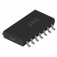
NJM2211M NJR, NJM2211M Datasheet - Page 4

NJM2211M
Manufacturer Part Number
NJM2211M
Description
IC FSK DEMOD/ TONE DECODER S014
Manufacturer
NJR
Datasheet
1.NJM2211D.pdf
(10 pages)
Specifications of NJM2211M
Function
Demodulator
Current - Supply
11mA
Voltage - Supply
4.5 V ~ 20 V
Package / Case
14-DMP
Lead Free Status / RoHS Status
Contains lead / RoHS non-compliant
Gain
-
Noise Figure
-
P1db
-
Lo Frequency
-
Rf Frequency
-
Available stocks
Company
Part Number
Manufacturer
Quantity
Price
Company:
Part Number:
NJM2211M-TE1
Manufacturer:
NJR
Quantity:
12 000
■ EQUIVALENT CIRCUIT
■ CIRCUIT FUNCTION
● Signal Input (Pin 2)
The input signal is AC coupled to this terminal. The internal impedance at pin 2 is 20kΩ, Recommended input signal
leveles in the range of 10mVrms to 3Vrms.
● Quadrature Phase Detector Output (Pin 3)
This is the high-impedance output of the quadrature phase detector, and is internally connected to the input of lock-detect
voltage comparator. In tone detection applications, pin 3 is connected to ground through a parallel combination of R
C
open circuited.
● Lock-Detect Output, Q (Pin 5)
The output at pin 5 is at a "high" state when the PLL is out of lock and goes to a "low" or conducting state when the PLL is
locked. It is an open collector type output and required a pull-up resistor, R
can sink up to 5mA of load current.
● Lock-Detect Complement, Q (Pin 6)
The output at pin 6 is the logic complement of the lock-detect output at pin 5. This output is also an open collector type
stage which can sink 5mA of load current in the low or "on" state.
● FSK Data Output (Pin 7)
This output is an open collector logic stage which requres a pull-up resistor, R
of load current. When decoding FSK signals the FSK data output will switch to a "high"or off state for low input frequency,
and will switch to a "low" or on state for high input frequency. If no input signal is present, the logic state at pin 7 is
indeterminate.
● FSK Comparator Input (Pin 8)
This is the high-impedance input to the FSK voltage comparator. Normally, an FSK post-detection or data filter is
connected between this terminal and the PLL phase-detector output (pin 11). This data filter is formed by R
Figure 1. The threshold voltage of the comparator is set by the internal reference voltage, V
D
- 4 -
(see Figure 1) to eliminate chatter at the lock-detect outputs. If this tone-detect section is not used, pin 3 can be left
L
, to V
L
, to V
+
for proper operation. In the "low" state it
+
for proper operation. It can sink 5mA
R
, available at pin 10.
Ver.2003-12-09
F
and C
D
and
F
of


