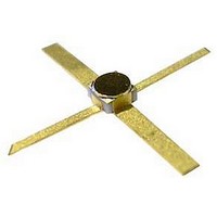
MSA-1120 Avago Technologies US Inc., MSA-1120 Datasheet - Page 3

MSA-1120
Manufacturer Part Number
MSA-1120
Description
AMP MMIC SI BIPOLAR 200-MIL BeO
Manufacturer
Avago Technologies US Inc.
Series
-r
Type
General Purposer
Datasheet
1.MSA-1120.pdf
(4 pages)
Specifications of MSA-1120
Gain
11.5dB ~ 13.5dB
Rf Type
ISM
Current - Supply
40mA ~ 75mA
Frequency
50MHz ~ 1.6GHz
Noise Figure
3.5dB ~ 4.5dB
P1db
16dBm ~ 17.5dBm
Package / Case
4-SMD (100 mil)
Test Frequency
500MHz
Voltage - Supply
4.5V ~ 6.5V
Frequency Range
50MHz To 1.6GHz
Noise Figure Typ
3.5dB
Power Dissipation Pd
650mW
Supply Current
75mA
Supply Voltage Range
4.5V To 6.5V
Number Of Channels
1
Frequency (max)
25GHz
Output Power
17.5@500MHzdBm
Power Supply Requirement
Single
Single Supply Voltage (min)
4.5V
Single Supply Voltage (typ)
5.5V
Single Supply Voltage (max)
6.5V
Package Type
BeO
Dual Supply Voltage (min)
Not RequiredV
Dual Supply Voltage (typ)
Not RequiredV
Dual Supply Voltage (max)
Not RequiredV
Pin Count
4
Mounting
Surface Mount
Lead Free Status / RoHS Status
Lead free / RoHS Compliant
Lead Free Status / RoHS Status
Lead free / RoHS Compliant, Lead free / RoHS Compliant
Available stocks
Company
Part Number
Manufacturer
Quantity
Price
Part Number:
MSA-1120
Manufacturer:
AVAGO/安华高
Quantity:
20 000
Company:
Part Number:
MSA-1120-BLK
Manufacturer:
AVAGO
Quantity:
1 020
Company:
Part Number:
MSA-1120-TR1
Manufacturer:
AMS
Quantity:
301
MSA-1120 Typical Scattering Parameters
3
Typical Performance, T
(unless otherwise noted)
Figure 1. Typical Power Gain vs. Frequency,
I
Figure 4. Output Power at 1 dB Gain Compression,
Noise Figure and Power Gain vs. Case Temperature,
f = 0.5 GHz, I
d
18
17
16
16
14
12
10
= 60 mA.
4
3
8
6
4
2
0
5
.02
1.000
1.500
.000
.500
3.000
Freq.
.0005
.005
.05
.050
.100
.00
.300
.400
.500
.600
.700
.800
.900
GHz
–55
.05
d
= 60 mA.
TEMPERATURE (C)
FREQUENCY (GHz)
0.1
+25
Mag
.78
.19
.05
.04
.04
.05
.07
.09
.10
.1
.14
.15
.17
.19
.5
.31
.35
.40
Z
O
S
= 75
A
0.5 1.0 2.0 3.0
11
= 25°C, Z
Z
O
–105
–113
–10
–17
–134
–140
–167
Ang
–1
–7
–56
–5
–56
–7
–84
–96
= 50
171
157
140
+125
P
NF
G
1 dB
P
O
13
12
11
= 50 Ω
19.6
13.8
1.9
1.5
1.5
1.4
1.4
1.3
1.1
1.0
11.8
11.6
11.4
11.1
dB
9.8
8.4
7.3
6.1
(Z
Figure 2. Device Current vs. Voltage.
100
Figure 5. Output Power at 1 dB Gain Compression
vs. Frequency.
O
80
60
40
20
22
20
18
16
14
12
0
= 50 Ω, T
0.1
0
Mag
T
T
T
9.53
4.91
4.44
4.3
4.
4.19
4.15
4.10
4.04
3.98
3.89
3.80
3.71
3.60
3.10
.64
.31
.0
I
I
I
S
d
d
C
C
C
d
21
= 75 mA
= 60 mA
= +125C
= +25C
= –55C
= 40 mA
0.2 0.3
A
2
= 5°C, I
FREQUENCY (GHz)
Ang
168
165
174
174
17
165
158
151
144
137
131
14
118
11
83
58
39
19
0.5
d
4
V
= 60 mA)
d
(V)
1.0
–5.1
–16.8
–16.5
–16.1
–16.
–16.1
–16.0
–15.9
–15.8
–15.6
–15.4
–15.
–15.0
–14.8
–14.0
–13.3
–1.8
–1.5
dB
6
2.0
.057
.144
.149
.156
.155
.157
.159
.161
.163
.166
.169
.173
.178
.181
.00
.16
.8
.36
Mag
S
12
8
Ang
–10
–16
–3
–3
50
11
3
1
1
3
3
1
Figure 6. Noise Figure vs. Frequency.
5.0
4.5
4.0
3.5
3.0
14
12
10
8
6
4
Figure 3. Power Gain vs. Current.
0.1
20
Mag
0.2 0.3
.79
.19
.06
.04
.04
.06
.09
.11
.13
.16
.18
.0
.
.4
.31
.35
.36
.36
40
FREQUENCY (GHz)
S
22
0.5
–101
–109
–117
–14
–130
–136
–14
–148
–174
I
Ang
60
d
–1
–7
–75
–79
–78
–91
163
148
134
(mA)
1.0
1.0 GHz,
80
1.0 GHz
2.0 GHz
0.1 GHz
0.5 GHz
I
I
I
d
d
d
= 75 mA
= 60 mA
= 40 mA
2.0
0.51
0.98
1.08
1.08
1.09
1.08
1.07
1.06
1.05
1.04
1.03
1.01
1.00
0.99
0.95
0.95
0.96
0.99
k


