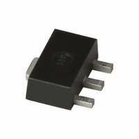
SGA-9189Z Sirenza Microdevices Inc, SGA-9189Z Datasheet - Page 2

SGA-9189Z
Manufacturer Part Number
SGA-9189Z
Description
IC AMP HBT SIGE 3GHZ SOT-89
Manufacturer
Sirenza Microdevices Inc
Datasheet
1.SGA-9189Z.pdf
(6 pages)
Specifications of SGA-9189Z
Current - Supply
180mA
Frequency
0Hz ~ 3GHz
Gain
13.2dB
Noise Figure
2.6dB
P1db
23.5 ~ 25.5dBm
Package / Case
SOT-89
Rf Type
WLL, WLAN
Test Frequency
1.95GHz
Voltage - Supply
5.5V
Lead Free Status / RoHS Status
Lead free / RoHS Compliant
Other names
599-1056-2
Available stocks
Company
Part Number
Manufacturer
Quantity
Price
Company:
Part Number:
SGA-9189Z
Manufacturer:
Skyworks
Quantity:
558
SGA-9189(Z)
Typical Performance with Engineering Application Circuit
Typical Performance with Engineering Application Circuit
Data above represents typical performance of the application circuits notes in Application Note AN-021. Refer to the applica-
tion note for additional RF data, PCB layouts, and BOMs for each application circuit. The application note also includes biasing
instructions and other key issues to be considered. For the latest application notes please visit our site at wwww.RFMD.com or
call your local sales representative.
2 of 6
Absolute Maximum Ratings
Max Base Current (IB)
Max Device Current (ICE)
Max Collector-Emitter Voltage (VCEO)
Max Collector-Base Voltage (VCBO)
Max Emitter-Base Voltage (VEBO)
Max Junction Temp (TJ)
Operating Temp Range (TL)
Max Storage Temp
*Note: Load condition1, Z
Operation of this device beyond any one of these limits may cause permanent dam-
Bias Conditions should also satisfy the following expression:
1
2
(MHz)
(MHz)
P
P
Freq
Freq
1960
2440
1960
2440
2140
OUT
OUT
945
945
age. For reliable continuous operation, the device voltage and current must not
exceed the maximum operating values specified in the table on page one.
I
D
V
=+10dBm per tone for V
=+6dBm per tone for V
D
<(T
J
Parameter
-T
L
)/R
VCE
VCE
(V)
(V)
5
5
5
5
3
3
3
TH
, j-l and T
1.20
1.00
0.80
0.60
0.40
0.20
0.00
L
Maximum Recommended Operational
=50Ω.
-40
(mA)
(mA)
ICQ
ICQ
CE
184
180
180
165
162
165
179
L
CE
=T
=3V, 1MHz tone spacing
=5V, 1MHz tone spacing
Operational Limit (Tj<130C)
LEAD
-10
7628 Thorndike Road, Greensboro, NC 27409-9421 · For sales or technical
support, contact RFMD at (+1) 336-678-5570 or sales-support@rfmd.com.
Dissipated Power
Lead Temperature (C)
(dBm)
(dBm)
P1dB
P1dB
20
25.8
25.5
25.4
25.4
22.1
22.4
23.2
50
See Graph
Rating
+150
+150
200
4.8
20
OIP3
(dBm)
OIP3
(dBm)
5
7
80
39.5
40.0
39.0
40.0
34.3
35.0
35.3
1
2
110
Gain
Gain
(dB)
(dB)
18.8
12.2
11.3
10.2
11.8
140
17.7
9.9
Unit
mA
mA
°C
°C
V
V
V
S11
(dB)
S11
(dB)
-14
-23
-20
-20
-18
-18
-20
Exceeding any one or a combination of the Absolute Maximum Rating conditions may
cause permanent damage to the device. Extended application of Absolute Maximum
Rating conditions to the device may reduce device reliability. Specified typical perfor-
mance or functional operation of the device under Absolute Maximum Rating condi-
tions is not implied.
RoHS status based on EUDirective2002/95/EC (at time of this document revision).
The information in this publication is believed to be accurate and reliable. However, no
responsibility is assumed by RF Micro Devices, Inc. ("RFMD") for its use, nor for any
infringement of patents, or other rights of third parties, resulting from its use. No
license is granted by implication or otherwise under any patent or patent rights of
RFMD. RFMD reserves the right to change component circuitry, recommended appli-
cation circuitry and specifications at any time without prior notice.
S22
(dB)
S22
(dB)
-26
-21
-14
-17
-11
-16
-15
Caution! ESD sensitive device.
Z
SOPT
(dB)
(dB)
NF
NF
2.1
2.4
2.6
2.7
2.1
2.2
2.6
B
18.1 + j3.4
5.6 - j15.1
8.1 - j16.0
E
7.6 - j11.2
7.8 - j13.1
C
6.8 -j0.85
ZSOPT
ZSOPT
9.6 - j1.6
(Ω)
(Ω)
Z
LOPT
EDS-101497 Rev I
22.8 + j0.7
11.0 + j1.4
19.3 - j2.9
23.8 - j9.0
23.1 - j2.7
21.0 - j6.5
ZSOPT
16 + j5.9
ZSOPT
(Ω)
(Ω)


