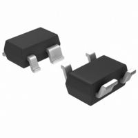
MGA-53543-TR1G Avago Technologies US Inc., MGA-53543-TR1G Datasheet - Page 12

MGA-53543-TR1G
Manufacturer Part Number
MGA-53543-TR1G
Description
IC AMP RFIC 1.9GHZ SOT-343
Manufacturer
Avago Technologies US Inc.
Datasheet
1.MGA-53543-TR1G.pdf
(14 pages)
Specifications of MGA-53543-TR1G
Gain
14dB ~ 17dB
Rf Type
Cellular, PCS
Current - Supply
40mA ~ 70mA
Frequency
0Hz ~ 2.4GHz
Noise Figure
1.5dB ~ 1.9dB
P1db
18.6dBm
Package / Case
SC-70-4, SC-82-4, SOT-323-4, SOT-343
Test Frequency
1.9GHz
Voltage - Supply
5V ~ 5.5V
Frequency Range
50MHz To 6GHz
Noise Figure Typ
1.5dB
Power Dissipation Pd
400mW
Supply Current
54mA
Supply Voltage Range
5V
Manufacturer's Type
Linear Amplifier
Number Of Channels
1
Frequency (max)
6GHz
Operating Supply Voltage (max)
5.5V
Package Type
SOT-343
Mounting
Surface Mount
Pin Count
3 +Tab
Noise Figure (typ)
1.9@2400MHzdB
Lead Free Status / RoHS Status
Lead free / RoHS Compliant
Lead Free Status / RoHS Status
Lead free / RoHS Compliant, Lead free / RoHS Compliant
Other names
516-1826-2
MGA-53543-TR1G
MGA-53543-TR1G
Available stocks
Company
Part Number
Manufacturer
Quantity
Price
Company:
Part Number:
MGA-53543-TR1G
Manufacturer:
AVAGO
Quantity:
15 600
Company:
Part Number:
MGA-53543-TR1G
Manufacturer:
AVAGO
Quantity:
11 800
Part Number:
MGA-53543-TR1G
Manufacturer:
AVAGO/安华高
Quantity:
20 000
1900 MHz LNA Design
The final example presented in this application note is a
PCS band low noise amplifier circuit. As in the 900 MHz
LNA example, the input is matched to Γ
MHz is given as .9 ∠-17° and the output is matched for
maximum linearity i.e. Γ
very similar to the 1900 MHz HLA. In fact, the only major
difference between the PCS HLA presented earlier and
this PCS LNA schematic is a 3.9nH inductor on the input.
The complete schematic is shown below.
RF
Figure 30. Schematic for 1900 MHz LNA design.
Table 6 shows the complete parts list used for the 1900
MHz low noise amplifier.
Table 6. Component parts list for the MGA-53453 LNA amplifier at 1900
MHz.
3.9 nH
47 nH
.Ω
. pF
8. pF
150 pF
1
in
3.9 nH
TOKO LL1608-FS3N9S
TOKO LL1005-FH47N
RHOM MCR01JR
Phycomp 040CG9C9B00
Phycomp 040CG89D9B00
Phycomp 040CG151J9B00
2.2 pF
1
3
53
2
4
+5V
L
. Biasing the DC supply is done
2.2Ω
47 nH
8.2 pF
150 pF
RF
out
opt
which at 1900
Performance of MGA-53543 at 1900 MHz
The typical noise figure for the 1900 MHz LNA is measured
to be 1.6 dB with OIP3 at a nominal 37 dBm. Figure 31
shows a measured gain of 14.8 dB and Figure 3 shows
the input and output return loss to be 16.4 dB and 11.3
dB respectively. P1dB is 18 dBm.
Figure 31. Gain, Noise Figure vs. Frequency for 1900 MHz LNA.
Figure 32. Input and Output Return Loss for 1900 MHz LNA.
Figure 22. Gain, Noise Figure vs Frequency
for 1900 MHz LNA.
Figure 23. Input and Output Return Loss for
1900 MHz LNA.
-10
-15
-20
-25
20
15
10
-5
5
0
0
1.6
1.6
1.8
1.8
FREQUENCY (GHz)
FREQUENCY (GHz)
2.0
2.0
2.2
2.2
S22
S11
Gain
NF
2.4
2.4
2.6
2.6


