STM32L152-EVAL STMicroelectronics, STM32L152-EVAL Datasheet - Page 62
STM32L152-EVAL
Manufacturer Part Number
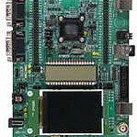
STM32L152-EVAL
Description
BOARD EVALUATION FOR STM32L
Manufacturer
STMicroelectronics
Type
MCUr
Specifications of STM32L152-EVAL
New! Us2012 Catalog Page
STM8L-Discovery_STM32L152-EVAL
Contents
Board
Processor To Be Evaluated
STM32L1xxx
Interface Type
UART
Operating Supply Voltage
2 V to 3.6 V
For Use With/related Products
STM32L
Lead Free Status / RoHS Status
Lead free / RoHS Compliant
Other names
497-10842


Electrical characteristics
62/107
Table 24.
1. Resonator characteristics given by the crystal/ceramic resonator manufacturer.
2. Based on characterization results, not tested in production.
3. The relatively low value of the RF resistor offers a good protection against issues resulting from use in a
4. t
For C
5 pF to 25 pF range (typ.), designed for high-frequency applications, and selected to match
the requirements of the crystal or resonator (see
same size. The crystal manufacturer typically specifies a load capacitance which is the
series combination of C
can be used as a rough estimate of the combined pin and board capacitance) when sizing
C
microcontrollers” available from the ST website www.st.com.
Symbol
I
t
f
DD(HSE)
SU(HSE)
OSC_IN
L1
I
HSE
R
g
humid environment, due to the induced leakage and the bias condition change. However, it is
recommended to take this point into account if the MCU is used in tough humidity conditions.
oscillation is reached. This value is measured for a standard crystal resonator and it can vary significantly
with the crystal manufacturer.
(4)
C
SU(HSE)
m
and C
F
L1
and C
Oscillator frequency
Feedback resistor
Recommended load
capacitance versus
equivalent serial resistance
of the crystal (R
HSE driving current
HSE oscillator power
consumption
Oscillator transconductance
Startup time
is the startup time measured from the moment it is enabled (by software) to a stabilized 8 MHz
L2
. Refer to the application note AN2867 “Oscillator design guide for ST
HSE 1-24 MHz oscillator characteristics
L2
, it is recommended to use high-quality external ceramic capacitors in the
Parameter
L1
S
)
(3)
and C
Doc ID 17659 Rev 4
L2
. PCB and MCU pin capacitance must be included (10 pF
V
DD
V
with 30 pF load
f
f
= 3.3 V, V
OSC
OSC
DD
Conditions
R
C = 20 pF
C = 10 pF
Startup
S
is stabilized
= 16 MHz
= 16 MHz
= 30
IN
Figure
= V
SS
(1)(2)
16). C
Min Typ
3.5
1
STM32L151xx, STM32L152xx
L1
200
20
1
and C
0.46 (stabilized)
0.7 (stabilized)
L2
2.5 (startup)
2.5 (startup)
are usually the
Max
24
3
MHz
Unit
mA
mA
mA
k
ms
pF
/V
Related parts for STM32L152-EVAL
Image
Part Number
Description
Manufacturer
Datasheet
Request
R

Part Number:
Description:
IAR� starter kit for STM32L EnergyLite 32-bit microcontrollers
Manufacturer:
STMICROELECTRONICS [STMicroelectronics]
Datasheet:

Part Number:
Description:
MCU, MPU & DSP Development Tools STM32L152VBT6 IAR 32KB Workbench
Manufacturer:
STMicroelectronics
Datasheet:

Part Number:
Description:
16/32-BITS MICROS
Manufacturer:
STMicroelectronics
Datasheet:
Part Number:
Description:
BOARD, EVAL, STM32L-DISCOVERY
Manufacturer:
STMicroelectronics
Datasheet:
Part Number:
Description:
STMicroelectronics [RIPPLE-CARRY BINARY COUNTER/DIVIDERS]
Manufacturer:
STMicroelectronics
Datasheet:
Part Number:
Description:
STMicroelectronics [LIQUID-CRYSTAL DISPLAY DRIVERS]
Manufacturer:
STMicroelectronics
Datasheet:

Part Number:
Description:
BOARD EVAL FOR MEMS SENSORS
Manufacturer:
STMicroelectronics
Datasheet:
Part Number:
Description:
NPN TRANSISTOR POWER MODULE
Manufacturer:
STMicroelectronics
Datasheet:
Part Number:
Description:
TURBOSWITCH ULTRA-FAST HIGH VOLTAGE DIODE
Manufacturer:
STMicroelectronics
Datasheet:
Part Number:
Description:
Manufacturer:
STMicroelectronics
Datasheet:
Part Number:
Description:
DIODE / SCR MODULE
Manufacturer:
STMicroelectronics
Datasheet:
Part Number:
Description:
DIODE / SCR MODULE
Manufacturer:
STMicroelectronics
Datasheet: