TWR-K60N512-KIT Freescale Semiconductor, TWR-K60N512-KIT Datasheet - Page 3
TWR-K60N512-KIT
Manufacturer Part Number
TWR-K60N512-KIT
Description
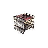
TOWER SYSTEM KIT K60N512
Manufacturer
Freescale Semiconductor
Series
Kinetisr
Type
MCUr
Specifications of TWR-K60N512-KIT
Contents
4 Boards, Documentation, DVD
Processor To Be Evaluated
K60
Data Bus Width
32 bit
Interface Type
RS-232, USB, CAN, I2C, SPI, UART
Dimensions
3.5 in x 3.5 in x 3.5 in
Operating Supply Voltage
1.71 V to 3.6 V
Silicon Manufacturer
Freescale
Core Architecture
ARM
Core Sub-architecture
Cortex - M4
Silicon Core Number
MK
Silicon Family Name
Kinetis - K60
Kit Contents
4x Brds, Cable, Docs
Rohs Compliant
Yes
For Use With/related Products
Freescale Tower System, K60N512
Lead Free Status / RoHS Status
Lead free / RoHS Compliant


List of Figures
Figure 1. Freescale Tower System Overview .............................................................................................. 4
Figure 2. Callouts on front side of the TWR-K60N512 ................................................................................ 5
Figure 3. Callouts on back side of the TWR-K60N512 ................................................................................ 6
Figure 4. TWR-K60N512 Block Diagram ...................................................................................................... 7
Figure 5. Infrared Port Implementation ................................................................................................... 10
List of Tables
Table 1. Cortex Debug+ETM Connector Pinout .......................................................................................... 9
Table 2. General Purpose TWRPI socket pinout ....................................................................................... 11
Table 3. Touch TWRPI socket pinout ........................................................................................................ 12
Table 4. Ethernet operation jumper settings ........................................................................................... 12
Table 5. TWR-K60N512 Jumper Table ...................................................................................................... 13
Table 6. I/O Connectors and Pin Usage Table........................................................................................... 14
Table 7. TWR-K60N512 Primary Connector Pinout .................................................................................. 16
Revision History
Revision
Date
Changes
1.0
Nov 9, 2010
Initial Release for PWA 700-26548 Rev A
TWR-K60N512 Tower Module User's Manual
Page 3 of 17
Related parts for TWR-K60N512-KIT
Image
Part Number
Description
Manufacturer
Datasheet
Request
R

Part Number:
Description:
Manufacturer:
Freescale Semiconductor, Inc
Datasheet:
Part Number:
Description:
Manufacturer:
Freescale Semiconductor, Inc
Datasheet:
Part Number:
Description:
Manufacturer:
Freescale Semiconductor, Inc
Datasheet:
Part Number:
Description:
Manufacturer:
Freescale Semiconductor, Inc
Datasheet:
Part Number:
Description:
Manufacturer:
Freescale Semiconductor, Inc
Datasheet:
Part Number:
Description:
Manufacturer:
Freescale Semiconductor, Inc
Datasheet:
Part Number:
Description:
Manufacturer:
Freescale Semiconductor, Inc
Datasheet:
Part Number:
Description:
Manufacturer:
Freescale Semiconductor, Inc
Datasheet:
Part Number:
Description:
Manufacturer:
Freescale Semiconductor, Inc
Datasheet:
Part Number:
Description:
Manufacturer:
Freescale Semiconductor, Inc
Datasheet:
Part Number:
Description:
Manufacturer:
Freescale Semiconductor, Inc
Datasheet:
Part Number:
Description:
Manufacturer:
Freescale Semiconductor, Inc
Datasheet:
Part Number:
Description:
Manufacturer:
Freescale Semiconductor, Inc
Datasheet:
Part Number:
Description:
Manufacturer:
Freescale Semiconductor, Inc
Datasheet:
Part Number:
Description:
Manufacturer:
Freescale Semiconductor, Inc
Datasheet: