TWR-K60N512-KIT Freescale Semiconductor, TWR-K60N512-KIT Datasheet - Page 12
TWR-K60N512-KIT
Manufacturer Part Number
TWR-K60N512-KIT
Description
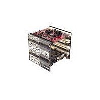
TOWER SYSTEM KIT K60N512
Manufacturer
Freescale Semiconductor
Series
Kinetisr
Type
MCUr
Specifications of TWR-K60N512-KIT
Contents
4 Boards, Documentation, DVD
Processor To Be Evaluated
K60
Data Bus Width
32 bit
Interface Type
RS-232, USB, CAN, I2C, SPI, UART
Dimensions
3.5 in x 3.5 in x 3.5 in
Operating Supply Voltage
1.71 V to 3.6 V
Silicon Manufacturer
Freescale
Core Architecture
ARM
Core Sub-architecture
Cortex - M4
Silicon Core Number
MK
Silicon Family Name
Kinetis - K60
Kit Contents
4x Brds, Cable, Docs
Rohs Compliant
Yes
For Use With/related Products
Freescale Tower System, K60N512
Lead Free Status / RoHS Status
Lead free / RoHS Compliant


2.10 Ethernet
The K60N512 features a 10/100 Mbps Ethernet MAC with MII and RMII interfaces. The TWR-K60N512
routes the RMII interface signals from the K60 MCU to the Primary Connector, allowing the connection
to an external Ethernet PHY device on a Tower peripheral module.
When the K60 Ethernet MAC is operating in RMII mode, synchronization of the MCU clock and the 50
MHz RMII transfer clock is important. The MCU input clock must be kept in phase with the 50 MHz
clock supplied to the external PHY. Therefore, the TWR-K60N512 provides the option (see description
for J6 in Table 5) to clock the MCU from an external clock from the CLKIN0 pin on the Primary
Connector. The Tower peripheral module implementing the RMII PHY device should drive a 50 MHz
clock on the CLKIN0 pin that is kept in phase with the clock supplied to the RMII PHY.
The TWR-SER module that comes as part of the TWR-K60N512-KIT provides a 10/100 Ethernet PHY
that can operate in either MII or RMII mode. By default the PHY is boot strapped to operate in MII
mode; therefore jumper configuration changes may be required. Table 4 shows the settings for proper
interoperability between the Ethernet interface on the TWR-SER and the TWR-K60N512.
TWR-K60N512 Tower Module User's Manual
Table 4. Ethernet operation jumper settings
Table 3. Touch TWRPI socket pinout
Tower Module
TWR-K60N512
TWR-SER
TWR-SER
TWR-SER
Pin
1
2
3
4
5
6
7
8
9
10
11
12
13
14
15
16
17
18
19
20
Description
5V VCC
3.3 V VCC
Electrode 0
3.3V VDDA
Electrode 1
VSS (Analog GND)
Electrode 2
Electrode 3
Electrode 4
Electrode 5
Electrode 6
Electrode 7
Electrode 8
Electrode 9
Electrode 10
Electrode 11
ADC: TWRPI ID 0
ADC: TWRPI ID 1
GND
Reset
Jumper
J12
J6
J2
J3
Setting
9-10
2-3
3-4
2-3
Page 12 of 17
Related parts for TWR-K60N512-KIT
Image
Part Number
Description
Manufacturer
Datasheet
Request
R

Part Number:
Description:
Manufacturer:
Freescale Semiconductor, Inc
Datasheet:
Part Number:
Description:
Manufacturer:
Freescale Semiconductor, Inc
Datasheet:
Part Number:
Description:
Manufacturer:
Freescale Semiconductor, Inc
Datasheet:
Part Number:
Description:
Manufacturer:
Freescale Semiconductor, Inc
Datasheet:
Part Number:
Description:
Manufacturer:
Freescale Semiconductor, Inc
Datasheet:
Part Number:
Description:
Manufacturer:
Freescale Semiconductor, Inc
Datasheet:
Part Number:
Description:
Manufacturer:
Freescale Semiconductor, Inc
Datasheet:
Part Number:
Description:
Manufacturer:
Freescale Semiconductor, Inc
Datasheet:
Part Number:
Description:
Manufacturer:
Freescale Semiconductor, Inc
Datasheet:
Part Number:
Description:
Manufacturer:
Freescale Semiconductor, Inc
Datasheet:
Part Number:
Description:
Manufacturer:
Freescale Semiconductor, Inc
Datasheet:
Part Number:
Description:
Manufacturer:
Freescale Semiconductor, Inc
Datasheet:
Part Number:
Description:
Manufacturer:
Freescale Semiconductor, Inc
Datasheet:
Part Number:
Description:
Manufacturer:
Freescale Semiconductor, Inc
Datasheet:
Part Number:
Description:
Manufacturer:
Freescale Semiconductor, Inc
Datasheet: