TWR-S08MM128 Freescale Semiconductor, TWR-S08MM128 Datasheet - Page 4
TWR-S08MM128
Manufacturer Part Number
TWR-S08MM128
Description
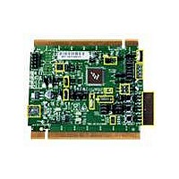
TOWER SYSTEM BOARD MC9S08MM128
Manufacturer
Freescale Semiconductor
Series
ColdFire®, Flexis™r
Type
MCUr
Datasheets
1.TWR-S08MM128.pdf
(12 pages)
2.TWR-S08MM128.pdf
(13 pages)
3.MC9S08MM128CMB.pdf
(52 pages)
Specifications of TWR-S08MM128
Contents
Board
Processor To Be Evaluated
9S08MM128
Data Bus Width
8 bit
Interface Type
USB, CAN
Silicon Manufacturer
Freescale
Core Architecture
Coldfire, HCS08
Core Sub-architecture
Coldfire V1, HCS08
Silicon Core Number
MCF51, MC9S08
Silicon Family Name
Flexis - MCF51MM, Flexis - S08MM
Rohs Compliant
Yes
For Use With/related Products
Freescale Tower System, MC9S08MM128
Lead Free Status / RoHS Status
Lead free / RoHS Compliant


2 Reference Documents
The documents listed below are available online. Refer to http://www.freescale.com/tower for the
latest revision of all Tower System documentation.
3 Hardware Features
This section provides more details about the features and functionality of the TWR‐S08MM128.
3.1
Two crystals are provided on the board for clocking the MC9S08MM128 device:
3.2
The TWR‐S08MM128 can be powered by the Open Source BDM (OSBDM) circuit via the Mini‐B USB
connector when stand‐alone. When assembled with the Tower System and the TWR‐SER is configured
to run USB device mode (J16 pin 3 and 4 connected), the Mini‐B USB connector is no longer used as a
power source and only used for OSBDM debugging purposes. In this case, the power will be supplied
from the Mini‐B USB from the TWR‐SER. Please plug in the Mini‐B USB connector from TWE‐SER before
plugging in the Mini‐B USB connector from TWR‐S08MM128.
A standard USB A male to Mini‐B male cable (provided) can be used to supply power from a USB host
or powered USB hub. Optionally, an AC to DC adapter with a USB A female receptacle (not provided)
can be used as the power source.
A jumper, J11, can be used to isolate the 3.3V supply from the microcontroller. This connection can be
used to measure the power usage of the MC9S08MM128 microcontroller.
3.3
An on‐board, MC9S08JM60 based OSBDM circuit provides a debug interface to the MC9S08MM128. A
standard USB A male to Mini‐B male cable (provided) can be used for debugging via the USB connector,
J17. Refer to Section 6 for information on other modes of operation of the OSBDM.
• TWR‐S08MM128 Schematics
• TWR‐S08MM128 Quick Start Guide
• TWR‐S08MM128‐KIT Lab Tutorial
• MC9S08MM128 Reference Manual
• MC9S08MM128 Data Sheet
• AN3561, USB Bootloader for the MC9S08JM60
1. A 16 MHz crystal connected to XTAL2 and EXTAL2 for system clocking
2. A 32.768kHz crystal connected to XTAL1 and EXTAL1 for TOD usage
Clocking
System Power
Debug Interface
TWR‐MC9S08MM128 User Manual
Page 4 of 13
Related parts for TWR-S08MM128
Image
Part Number
Description
Manufacturer
Datasheet
Request
R

Part Number:
Description:
Development Boards & Kits - S08 / S12 S08PT60 Tower Kit
Manufacturer:
Freescale Semiconductor
Datasheet:
Part Number:
Description:
Development Boards & Kits - S08 / S12 S08PT60Tower MCU mod
Manufacturer:
Freescale Semiconductor
Datasheet:
Part Number:
Description:
TOWER UNIVERSAL RS08/S08
Manufacturer:
Freescale Semiconductor
Datasheet:

Part Number:
Description:
Manufacturer:
Freescale Semiconductor, Inc
Datasheet:
Part Number:
Description:
Manufacturer:
Freescale Semiconductor, Inc
Datasheet:
Part Number:
Description:
Manufacturer:
Freescale Semiconductor, Inc
Datasheet:
Part Number:
Description:
Manufacturer:
Freescale Semiconductor, Inc
Datasheet:
Part Number:
Description:
Manufacturer:
Freescale Semiconductor, Inc
Datasheet:
Part Number:
Description:
Manufacturer:
Freescale Semiconductor, Inc
Datasheet:
Part Number:
Description:
Manufacturer:
Freescale Semiconductor, Inc
Datasheet:
Part Number:
Description:
Manufacturer:
Freescale Semiconductor, Inc
Datasheet:
Part Number:
Description:
Manufacturer:
Freescale Semiconductor, Inc
Datasheet:
Part Number:
Description:
Manufacturer:
Freescale Semiconductor, Inc
Datasheet:
Part Number:
Description:
Manufacturer:
Freescale Semiconductor, Inc
Datasheet:
Part Number:
Description:
Manufacturer:
Freescale Semiconductor, Inc
Datasheet: