78M6612-DB/OMU-USB Maxim Integrated Products, 78M6612-DB/OMU-USB Datasheet - Page 55
78M6612-DB/OMU-USB
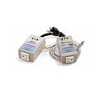
Manufacturer Part Number
78M6612-DB/OMU-USB
Description
KIT DEMO OUTLET MEASUREMENT OMU1
Manufacturer
Maxim Integrated Products
Datasheets
1.78M6612-IMF.pdf
(111 pages)
2.78M6612-EVM-1.pdf
(58 pages)
3.78M6612-DBOMU-USB.pdf
(30 pages)
4.78M6612-DBOMU-USB.pdf
(4 pages)
Specifications of 78M6612-DB/OMU-USB
Data Bus Width
8 bit
Interface Type
USB
Tool Type
Demonstration Board
Core Architecture
8051
Cpu Core
80515
Lead Free Status / RoHS Status
Lead free / RoHS Compliant


DS_6612_001
78M6612 Data Sheet
While PLL_OK = 0, the I/O RAM bits ADC_E and CE_E are held in zero state disabling both ADC and
CE. When PLL_OK falls, the CE program counter is cleared immediately and all FIR processing halts.
Figure 19
shows the functional blocks active in BROWNOUT mode.
MISSION
RESET
V3P3SYS
falls
V1 > VBIAS
IE_PLLRISE
IE_PLLFALL
V1 <= VBIAS
V3P3SYS
V3P3SYS
rises
rises
LCD_ONLY
BROWNOUT
V3P3SYS
rises
RESET &
VBAT_OK
IE_WAKE
SLEEP or
VBAT_OK
timer
LCD
timer
VBAT_OK
VBAT_OK
RESET &
VBAT_OK
SLEEP
Figure 18: Operation Modes State Diagram
2.3.2 LCD Mode
In LCD mode, the data contained in the LCD_SEG registers is displayed, i.e. up to four LCD segments
connected to each of the pins SEG18 and SEG19 can be made to blink without the involvement of the
MPU, which is disabled in LCD mode.
This mode can be exited only by system power up or by a timeout of the wake-up timer.
Figure 20
shows
the functional blocks active in LCD mode.
2.3.3 SLEEP Mode
In SLEEP mode, the battery current is minimized and only the Oscillator and RTC functions are active.
This mode can be exited only by system power-up or by a timeout of the wake-up timer.
Figure 21
shows
the functional blocks active in SLEEP mode.
Rev. 1.2
55
Related parts for 78M6612-DB/OMU-USB
Image
Part Number
Description
Manufacturer
Datasheet
Request
R

Part Number:
Description:
KIT DEMO OUTLET MEAS OMU1-S-RF
Manufacturer:
Maxim Integrated Products
Datasheet:

Part Number:
Description:
IC POWER MEASUREMENT AC 68-QFN
Manufacturer:
Maxim Integrated Products
Datasheet:

Part Number:
Description:
The Teridian™ 78M6612 is a highly integrated, single-phase, power and energy measurement and monitoring system-on-chip (SoC) that includes a 32-bit compute engine (CE), an MPU core, RTC, and flash
Manufacturer:
Maxim
Datasheet:

Part Number:
Description:
IC POWER MEASUREMENT AC 64-LQFP
Manufacturer:
Maxim Integrated Products
Datasheet:
Part Number:
Description:
IC POWER MEASUREMENT AC 68-QFN
Manufacturer:
Maxim Integrated Products
Datasheet:

Part Number:
Description:
IC POWER MEASUREMENT AC 64-LQFP
Manufacturer:
Maxim Integrated Products
Datasheet:
Part Number:
Description:
Current & Power Monitors & Regulators
Manufacturer:
Maxim Integrated Products
Datasheet:
Part Number:
Description:
Current & Power Monitors & Regulators 2 Out Sgl Phase Pwr & Energy Msrmt IC
Manufacturer:
Maxim Integrated Products
Datasheet:
Part Number:
Description:
Current & Power Monitors & Regulators
Manufacturer:
Maxim Integrated Products
Datasheet:
Part Number:
Description:
Current & Power Monitors & Regulators
Manufacturer:
Maxim Integrated Products
Datasheet:
Part Number:
Description:
Current & Power Monitors & Regulators
Manufacturer:
Maxim Integrated Products
Datasheet:
Part Number:
Description:
Current & Power Monitors & Regulators 2 Out Sgl Phase Pwr & Energy Msrmt IC
Manufacturer:
Maxim Integrated Products
Datasheet:
Part Number:
Description:
Current & Power Monitors & Regulators
Manufacturer:
Maxim Integrated Products
Datasheet:
Part Number:
Description:
Current & Power Monitors & Regulators
Manufacturer:
Maxim Integrated Products
Datasheet:
Part Number:
Description:
Current & Power Monitors & Regulators 2 Out Sgl Phase Pwr & Energy Msrmt IC
Manufacturer:
Maxim Integrated Products
Datasheet: