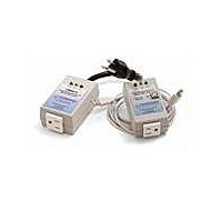
78M6612-DB/OMU-USB Maxim Integrated Products, 78M6612-DB/OMU-USB Datasheet - Page 5

78M6612-DB/OMU-USB
Manufacturer Part Number
78M6612-DB/OMU-USB
Description
KIT DEMO OUTLET MEASUREMENT OMU1
Manufacturer
Maxim Integrated Products
Datasheets
1.78M6612-IMF.pdf
(111 pages)
2.78M6612-EVM-1.pdf
(58 pages)
3.78M6612-DBOMU-USB.pdf
(30 pages)
4.78M6612-DBOMU-USB.pdf
(4 pages)
Specifications of 78M6612-DB/OMU-USB
Data Bus Width
8 bit
Interface Type
USB
Tool Type
Demonstration Board
Core Architecture
8051
Cpu Core
80515
Lead Free Status / RoHS Status
Lead free / RoHS Compliant
UG_6612_ 017
1 Introduction
This document describes the firmware 6612_OMU_S2+2_URT_V1_14, which can be used with the
Teridian 78M6612 power and energy measurement IC. This firmware provides simple methods for
calibration, relay control, and access to measurement data such as Watts, Voltage, Current, accumulated
Energy and line frequency. It is optimized for measurement of up to two single phase AC loads using
current shunts as the current sensors, but Current Transformer (CT) sensors may also be used if desired.
All measurement calculations are computed by the 78M6612 and communicated to the host processor
over a serial interface (UART0) on the TX and RX pins of the 78M6612 device. RTC (real time clock),
LCD Driver, and Battery Modes are not supported by this firmware. Additional 78M6612 hardware
utilized by this firmware includes:
The following sections detail the commands to be sent by the host to configure the 78M6612 and for
accessing measurement information.
2 Description of Basic Measurement Equations
The Teridian 78M6612 with firmware 6612_OMU_S2+2_URT_V1_14 provides the user with two types of
continuously updating measurement data (on 1 second increments by default). One is defined as
“Narrowband” (NB) and the other is defined as “Wideband” (WB).
Table 1 lists the basic measurement equations for the Narrowband and the Wideband methods.
Both types of measurement outputs are continuously available to the user. To obtain measurement
outputs, the serial UART interface between the 78M6612 and the host processor must be set up and is
described in the next section.
Rev. 1.0
•
•
•
•
DIO20 used as a configurable status alarm output pin
DIO4, DIO5, and DIO8 as LED outputs for Active, Ready, and Fault status
DIO7 and DIO19 used as configurable relay control ouputs
DIO6 used as an optional pulse output
Narrowband measurements are typically used by utilities where the measured waveforms are
assumed to be sinusoidal.
Wideband measurements are generally of interest when measuring nonlinear systems such as
switched mode power supplies that tend to have non-sinusoidal waveforms. This firmware
utilizes an effective sampling rate of 3641 samples per second.
Symbol
PA
PF
V
P
Q
S
I
Power Factor
RMS Voltage
RMS Current
Active Power
Phase Angle
Parameter
Apparent
Reactive
Table 1: Measurement Equations Definitions
Power
Power
6612_OMU_S2+2_URT_V1_14 Firmware Description Document
Narrowband Equation
Q = ∑
P = ∑
S = √(P
ACOS (P/S)
(i
V = √∑
(t) *
I = S/V
(i
P/S
(t) *
v
2
v
(t)shift 90º)
+ Q
(t)
v
2
(t))
2
)
Wideband Equation
P = ∑
Q = √(S
ACOS (P/S)
V = √∑
I = √∑
S = V * I
(i
P/S
(t) *
2
i
v
(t)
– P
(t)
2
v
2
(t))
2
)
5


