STEVAL-IHM029V1 STMicroelectronics, STEVAL-IHM029V1 Datasheet - Page 87
STEVAL-IHM029V1
Manufacturer Part Number
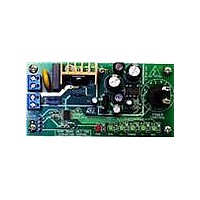
STEVAL-IHM029V1
Description
BOARD DEMO MOTOR CTRL VIPER16L
Manufacturer
STMicroelectronics
Series
VIPer™ plusr
Type
Other Power Managementr
Datasheets
1.T1235H-6G-TR.pdf
(10 pages)
2.STM8S103F2P6TR.pdf
(113 pages)
3.STEVAL-IHM029V1.pdf
(4 pages)
Specifications of STEVAL-IHM029V1
Main Purpose
Power Management, Motor Control
Embedded
Yes, MCU, 8-Bit
Utilized Ic / Part
STM8S103F2, T1235H
Primary Attributes
Universal Motor Control, 90 ~ 265 VAC Input, 2000 W Output
Secondary Attributes
LED Status Indicators
Operating Supply Voltage
90 V to 265 V
Product
Power Management Development Tools
Lead Free Status / RoHS Status
Lead free / RoHS Compliant
For Use With/related Products
STM8S103F2
Other names
497-10752
Available stocks
Company
Part Number
Manufacturer
Quantity
Price


STM8S103K3 STM8S103F3 STM8S103F2
10.3.11
10.3.11.1
10.3.11.2
3. End point correlation line
EMC characteristics
Susceptibility tests are performed on a sample basis during product characterization.
Functional EMS (electromagnetic susceptibility)
While executing a simple application (toggling 2 LEDs through I/O ports), the product is
stressed by two electromagnetic events until a failure occurs (indicated by the LEDs).
•
•
A device reset allows normal operations to be resumed. The test results are given in the table
below based on the EMS levels and classes defined in application note AN1709 (EMC design
guide for STMicrocontrollers).
Designing hardened software to avoid noise problems
EMC characterization and optimization are performed at component level with a typical
application environment and simplified MCU software. It should be noted that good EMC
performance is highly dependent on the user application and the software in particular.
Therefore it is recommended that the user applies EMC software optimization and
prequalification tests in relation with the EMC level requested for his application.
E
curves.
E
E
E
one.
E
point correlation line.
FESD: Functional electrostatic discharge (positive and negative) is applied on all pins of
the device until a functional disturbance occurs. This test conforms with the IEC 61000-4-2
standard.
FTB: A burst of fast transient voltage (positive and negative) is applied to V
through a 100 pF capacitor, until a functional disturbance occurs. This test conforms with
the IEC 61000-4-4 standard.
T
O
G
D
L
= Integral linearity error: maximum deviation between any actual transition and the end
= Total unadjusted error: maximum deviation between the actual and the ideal transfer
= Differential linearity error: maximum deviation between actual steps and the ideal
= Offset error: deviation between the first actual transition and the first ideal one.
= Gain error: deviation between the last ideal transition and the last actual one.
V AIN
R AIN
C AIN
Figure 44: Typical application with ADC
DocID15441 Rev 6
AINx
V DD
V T
0.6 V
V T
0.6 V
I L
± 1 µA
conversion
10-bit A/D
Electrical characteristics
STM8
C ADC
DD
and V
87/113
SS
Related parts for STEVAL-IHM029V1
Image
Part Number
Description
Manufacturer
Datasheet
Request
R

Part Number:
Description:
BOARD EVAL FOR MEMS SENSORS
Manufacturer:
STMicroelectronics
Datasheet:

Part Number:
Description:
KIT DEV STARTER ST10F276Z5
Manufacturer:
STMicroelectronics
Datasheet:

Part Number:
Description:
BOARD EVAL HDMI $ VIDEO SWITCH
Manufacturer:
STMicroelectronics
Datasheet:

Part Number:
Description:
BOARD DEMO ACCELEROMETER DIL24
Manufacturer:
STMicroelectronics
Datasheet:

Part Number:
Description:
BOARD STLM75/STDS75/ST72F651
Manufacturer:
STMicroelectronics
Datasheet:

Part Number:
Description:
EVAL BOARD 3AXIS MEMS ACCELLRMTR
Manufacturer:
STMicroelectronics
Datasheet:

Part Number:
Description:
BOARD EVAL 8BIT MICRO + TDE1708
Manufacturer:
STMicroelectronics
Datasheet:

Part Number:
Description:
EVAL BOARD A/D TS4657
Manufacturer:
STMicroelectronics
Datasheet:

Part Number:
Description:
BOARD ADAPTER 20DIP LIS3LV02DL
Manufacturer:
STMicroelectronics
Datasheet:

Part Number:
Description:
BOARD DEMO STM8S207R6/LIS331DLH
Manufacturer:
STMicroelectronics
Datasheet:

Part Number:
Description:
STMicroelectronics [RIPPLE-CARRY BINARY COUNTER/DIVIDERS]
Manufacturer:
STMicroelectronics
Datasheet:
Part Number:
Description:
STMicroelectronics [LIQUID-CRYSTAL DISPLAY DRIVERS]
Manufacturer:
STMicroelectronics
Datasheet:
Part Number:
Description:
BOARD EVAL FOR MEMS SENSORS
Manufacturer:
STMicroelectronics
Datasheet: