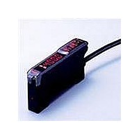
E3X-DA41-N Omron, E3X-DA41-N Datasheet - Page 10

E3X-DA41-N
Manufacturer Part Number
E3X-DA41-N
Description
PREWIRED DIGITAL PNP FO AMP
Manufacturer
Omron
Series
E3X-DA-Nr
Type
Photoelectric Sensorr
Specifications of E3X-DA41-N
Output Type
PNP
Amplifier Type
Standard
Voltage - Supply
12 V ~ 24 V
Current - Supply
40mA
Mounting Type
DIN Rail
Output
PNP
Light Source
Red LED
Connection
Prewired Cable
Output Configuration
PNP
Sensor Output
PNP
Sensor Input
Fiber Optic
Supply Voltage Max
24V
Supply Voltage Min
12V
Fiber Optic Sensor Type
Photoelectric Sensor
Rohs Compliant
Yes
Lead Free Status / RoHS Status
Lead free / RoHS Compliant
Lead Free Status / RoHS Status
Lead free / RoHS Compliant, Lead free / RoHS Compliant
Other names
E3XDA41N
Available stocks
Company
Part Number
Manufacturer
Quantity
Price
Company:
Part Number:
E3X-DA41-N
Manufacturer:
OMRON
Quantity:
374
PNP output
Note: With E3X-DA#TW models, only channel 1 is output when set for area sensing operation.
Connectors (Sensor I/O Connectors)
A-428
E3X-DA41-N
E3X-DAB41-N
E3X-DAG41-N
E3X-DAH41-N
E3X-DA41V
E3X-DA8
E3X-DAB8
E3X-DAG8
E3X-DAH8
E3X-DA44V
E3X-DA51-N
E3X-DA9
E3X-DA41TW
E3X-DA8TW
3
4
Model
L ON The range between the CH1 and CH2 thresholds turns ON
D ON The range between the CH1 and CH2 thresholds turns OFF (CH2 is always OFF)
2
1
1
2
3
4
Output transis-
tor Status
Light ON
Dark ON
Light ON
Dark ON
Light ON
Dark ON
XS3F-M421-402A
XS3F-M421-405A
XS3F-M422-402A
XS3F-M422-405A
Operation
Indicator
(orange)
Output
transistor
Load
(relay)
Operation
Indicator
(orange)
Output
transistor
Load
(relay)
Operation
Indicator
(orange)
Output
transistor
Load
(relay)
CH1/
CH2
Operation
Indicator
(orange)
Output
transistor
Load
(relay)
Operation
Indicator
(orange)
Output
transistor
Load
(relay)
CH1/
CH2
Operation
Indicator
(orange)
Output
transistor
Load
(relay)
No incident light
No incident light
No incident light
No incident light
Incident light
Incident light
Incident light
Incident light
No incident light
No incident light
Incident light
Release
Release
Operate
Release
Operate
Release
Release
ncident light
Operate
Operate
Operate
Operate
Release
Timing chart
OFF
OFF
OFF
OFF
OFF
OFF
OFF
OFF
OFF
OFF
OFF
OFF
ON
ON
ON
ON
ON
ON
ON
ON
ON
ON
ON
ON
(Between blue and black)
(Between blue and black)
(Between blue and black)
(Between blue and black)
(Between blue and black)
(Between blue and black)
Color of cable
conductors
T
T
T
T
T
T
Brown
White
Blue
Black
Mode selection
switch
(LIGHT ON)
(LIGHT ON)
(LIGHT ON)
(DARK ON)
(DARK ON)
(DARK ON)
D ON
D ON
D ON
L ON
L ON
L ON
Note: Pin 2 is open.
For DC
Class
Note: Load resistance: 10k W min.
Display
Display
Display
jacket color
Wire, outer
Operation
Indicator
(orange)
Brown
White
Black
Blue
Connector Pin Arrangement
Connector
Main
circuit
Main
circuit
Main
circuit
pin No.
Operation Indicator (orange)
Operation Indicator (orange)
Operation Indicator (orange)
Note: Pin 2 is not used.
A
B
C
D
Advanced Photoelectric Sensors
Output circuit
Power sup-
Power sup-
Application
ply (0 V)
ply (+V)
Output
-
47 W
1
4
3
1
Monitor output
Brown
Black
Orange
Blue
Brown
Black
Orange
Blue
Brown
Black
Blue
2
Control
output 1
Control
output 2
1 to 5 V
4
3
Control output
Control output
Load
Load
(see note)
Load
Load
Load
12 to 24
VDC
12 to 24
VDC
12 to 24
VDC


