E3X-A21 Omron, E3X-A21 Datasheet - Page 16
E3X-A21
Manufacturer Part Number
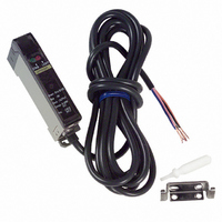
E3X-A21
Description
SENSOR PHOTO AMP USE W/E32 FIBER
Manufacturer
Omron
Type
Fiber Optic Photoelectric Sensorr
Series
E3Xr
Datasheet
1.E3X-A21.pdf
(17 pages)
Specifications of E3X-A21
Output Type
NPN
Amplifier Type
Standard
Voltage - Supply
10 V ~ 30 V
Current - Supply
35mA
Mounting Type
DIN Rail
Features
High Performance Amplifier Has Fast
Light Source
Pulse Modulated Red LED
Connection
5 Conductor Cable
Output Configuration
NPN
Sensor Output
NPN LO
Peak Reflow Compatible (260 C)
No
Sensor Housing
Rectangular
Sensor Input
Fiber Optic
Supply Voltage Max
30V
Leaded Process Compatible
No
Switch Terminals
Cable
Supply Voltage Min
10V
Rohs Compliant
No
Fiber Optic Sensor Type
Photoelectric
Lead Free Status / RoHS Status
Contains lead / RoHS compliant by exemption
Lead Free Status / RoHS Status
Contains lead / RoHS non-compliant, Contains lead / RoHS compliant by exemption
Other names
E3XA21
Z1116
Z1116


E3X
Connection
Do not pull or press the Fiber Units. The Fiber Units have a
withstand force of 1 kg or 3 kg (pay utmost attention because
the fibers are thin).
Do not bend the Fiber Units beyond the permissible bending
radius.
Do not bend the edge of the Fiber Units.
Do not apply excess force on the Fiber Units.
The Fiber Head could be broken by excessive
vibration. To prevent this, the following is effective:
Incorrect
Correct
Incorrect
Correct
A one-turn loop can
absorb vibrations
Amplifier
Fiber unit
Nylon wireholder
40 mm max.
20 mm max.
Metal holder
Tape
Fiber unit
17
Mounting
Removal
By pulling back the lock (yellow) on the bottom with a flat blade
screwdriver, the amplifier can be removed with ease.
In the case of side mounting, attach the mounting bracket on
the amplifier first, and secure the amplifier with M3 screws and
washers. The diameter of the washers should be 6 mm max.
Others
When power is off:
The moment power is turned off, the E3X could output a pulse
signal which could affect the operation of the devices
connected to it. This will happen more often if power is supplied
to the E3X from an external power supply, thus affecting the
connected timer and counter. Use a built-in power supply as
much as possible to avoid this.
If power is supplied to a photoelectric sensor through a cord
that is wired together with other power lines in the same duct,
the cord will be influenced by the power lines and
malfunctioning of the photoelectric sensor or damage could
result. Wire the cord separately or use a sealed cord to supply
power to the photoelectric sensor.
If the case of the cord is extended, use a wire with 0.3 mm
max.. The total length of the cord should be 100 m max.
Power supply:
If a standard switching regulator is used as a power supply, the
frame ground (FG) terminal and the ground (G) terminal must
be grounded, or otherwise the E3X can malfunction, influenced
by the switching noise of the power supply.
The supplied voltage must be within the rated voltage range.
Unregulated full- or half-wave rectifiers must not be used as
power supplies.
Do not use a hammer to hit the amplifier when mounting or the
amplifier will loose watertightness.
AMPLIFIER UNITS
1.
2.
Power line
Mount the front part on the mounting bracket (sold
together) or a DIN rail.
Press the back part onto the mounting bracket or the
DIN rail.
Washers (6 dia. max.)
Din rail
E3X
2
17
Related parts for E3X-A21
Image
Part Number
Description
Manufacturer
Datasheet
Request
R

Part Number:
Description:
EXPANDABLE A/D NPN FO AMP
Manufacturer:
Omron
Datasheet:

Part Number:
Description:
EXPANDABLE A/D PNP FO AMP
Manufacturer:
Omron
Datasheet:

Part Number:
Description:
PREWIRED A/D PNP FO AMP
Manufacturer:
Omron
Datasheet:

Part Number:
Description:
PREWIRED A/D NPN FO AMP
Manufacturer:
Omron
Datasheet:

Part Number:
Description:
Industrial Photoelectric Sensors Power + input conn Master 4 cond 2M
Manufacturer:
Omron
Datasheet:
Part Number:
Description:
Industrial Photoelectric Sensors For additional amps Slave 2 cond 2M
Manufacturer:
Omron
Datasheet:

Part Number:
Description:
SENSOR PHOTOAMP FIBER 2M CBL
Manufacturer:
Omron
Datasheet:

Part Number:
Description:
SENSOR PHOTO AMP FIBEROPTC W/TMR
Manufacturer:
Omron
Datasheet:
Part Number:
Description:
RED LED NPN PREWIRE PTUNE
Manufacturer:
Omron
Datasheet:

Part Number:
Description:
G6S-2GLow Signal Relay
Manufacturer:
Omron Corporation
Datasheet:
Part Number:
Description:
Compact, Low-cost, SSR Switching 5 to 20 A
Manufacturer:
Omron Corporation
Datasheet:
Part Number:
Description:
Manufacturer:
Omron Corporation
Datasheet: