E3X-A21 Omron, E3X-A21 Datasheet - Page 15
E3X-A21
Manufacturer Part Number
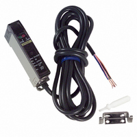
E3X-A21
Description
SENSOR PHOTO AMP USE W/E32 FIBER
Manufacturer
Omron
Type
Fiber Optic Photoelectric Sensorr
Series
E3Xr
Datasheet
1.E3X-A21.pdf
(17 pages)
Specifications of E3X-A21
Output Type
NPN
Amplifier Type
Standard
Voltage - Supply
10 V ~ 30 V
Current - Supply
35mA
Mounting Type
DIN Rail
Features
High Performance Amplifier Has Fast
Light Source
Pulse Modulated Red LED
Connection
5 Conductor Cable
Output Configuration
NPN
Sensor Output
NPN LO
Peak Reflow Compatible (260 C)
No
Sensor Housing
Rectangular
Sensor Input
Fiber Optic
Supply Voltage Max
30V
Leaded Process Compatible
No
Switch Terminals
Cable
Supply Voltage Min
10V
Rohs Compliant
No
Fiber Optic Sensor Type
Photoelectric
Lead Free Status / RoHS Status
Contains lead / RoHS compliant by exemption
Lead Free Status / RoHS Status
Contains lead / RoHS non-compliant, Contains lead / RoHS compliant by exemption
Other names
E3XA21
Z1116
Z1116


16
E3X
Precautions
Tightening Force
The tightening force applied to the Fiber Unit should be as
follows:
Use a proper-sized spanner.
Fiber units
M3/M4 screw
M6 screw
2-mm dia. column
3-mm dia. column
E32-D14L
E32-T12F
E32-D12F
E32-T16
E32-R21
E32-M21
E32-L25A
FIBER UNITS
Screw-mounting Model
Column Model
Nuts
(attachment)
Retaining screw
(M 3 max.)
Spring mounting clip
Clamping torque
8 kgf • cm max. (0.78 N • m)
10 kgf • cm max. (0.98 N • m)
3 kgf • cm max. (0.29 N • m)
3 kgf • cm max. (0.29 N • m)
10 kgf • cm max. (0.98 N • m)
8 kgf • cm max. (0.78 N • m)
8 kgf • cm max. (0.78 N • m)
5 kgf • cm max. (0.49 N • m)
6 kgf • cm max. (0.59 N • m)
Up to 5 mm to the tip: 5 kgf • cm
max. (0.49 N • m)
Up to 5 mm from the tip: 8 kgf • cm
max. (0.78 N • m)
8 kgf • cm max. (0.78 N • m)
Toothed washers
Clamping torque
3 kgf • cm max.
16
Fiber Connection and Disconnection
The E3X amplifier has a lever lock. Connect or disconnect the
fibers to or from the E3X amplifier using the following
procedures:
1. Connection
Insert the fibers into the E3X amplifier and press the lever
lock until the amplifier clicks to lock the fibers. The fibers will
have insertion marks when they are cut with the E39-F4
(Fiber Cutter). The portion from the tips to the insertion mark
should be inserted to the E3X.
2. Disconnection
Raise the lock lever to unlock the fibers before pulling
them out.
Fiber Insertion
If the portion from the tip to the insertion mark of the fibers are
not inserted into the amplifier unit, the sensing distance will be
reduced.
Locked
Lever lock
Fiber
Unlocked
Insertion mark
E3X
Related parts for E3X-A21
Image
Part Number
Description
Manufacturer
Datasheet
Request
R

Part Number:
Description:
EXPANDABLE A/D NPN FO AMP
Manufacturer:
Omron
Datasheet:

Part Number:
Description:
EXPANDABLE A/D PNP FO AMP
Manufacturer:
Omron
Datasheet:

Part Number:
Description:
PREWIRED A/D PNP FO AMP
Manufacturer:
Omron
Datasheet:

Part Number:
Description:
PREWIRED A/D NPN FO AMP
Manufacturer:
Omron
Datasheet:

Part Number:
Description:
Industrial Photoelectric Sensors Power + input conn Master 4 cond 2M
Manufacturer:
Omron
Datasheet:
Part Number:
Description:
Industrial Photoelectric Sensors For additional amps Slave 2 cond 2M
Manufacturer:
Omron
Datasheet:

Part Number:
Description:
SENSOR PHOTOAMP FIBER 2M CBL
Manufacturer:
Omron
Datasheet:

Part Number:
Description:
SENSOR PHOTO AMP FIBEROPTC W/TMR
Manufacturer:
Omron
Datasheet:
Part Number:
Description:
RED LED NPN PREWIRE PTUNE
Manufacturer:
Omron
Datasheet:

Part Number:
Description:
G6S-2GLow Signal Relay
Manufacturer:
Omron Corporation
Datasheet:
Part Number:
Description:
Compact, Low-cost, SSR Switching 5 to 20 A
Manufacturer:
Omron Corporation
Datasheet:
Part Number:
Description:
Manufacturer:
Omron Corporation
Datasheet: